

Part Three
(Fault Picking & Seismic Artifacts)
Identification & Picking of Faults on Seismic Data
In extensional tectonic regimes (σ1 vertical), in which the sediments are lengthened and, sometimes, in compressional tectonic regimes (shortening), the fault picking on seismic lines can be used as a seismic stratigraphy tool, predicting reservoir-rocks, source-rocks and morphological of traps by juxtaposition. It, strongly, suggests:
a) The lithological changes in the upper faulted blocks (hangingwall) and
b) The correlation of seismic intervals.
But what is a fault ?
In the field, a fault can be defined by the fracture or fracture zone along which the faulted blocks (hanging and footwall) move, relatively to each other, in a manner, more or less, parallel to the direction of the fracture (Figure 086)...
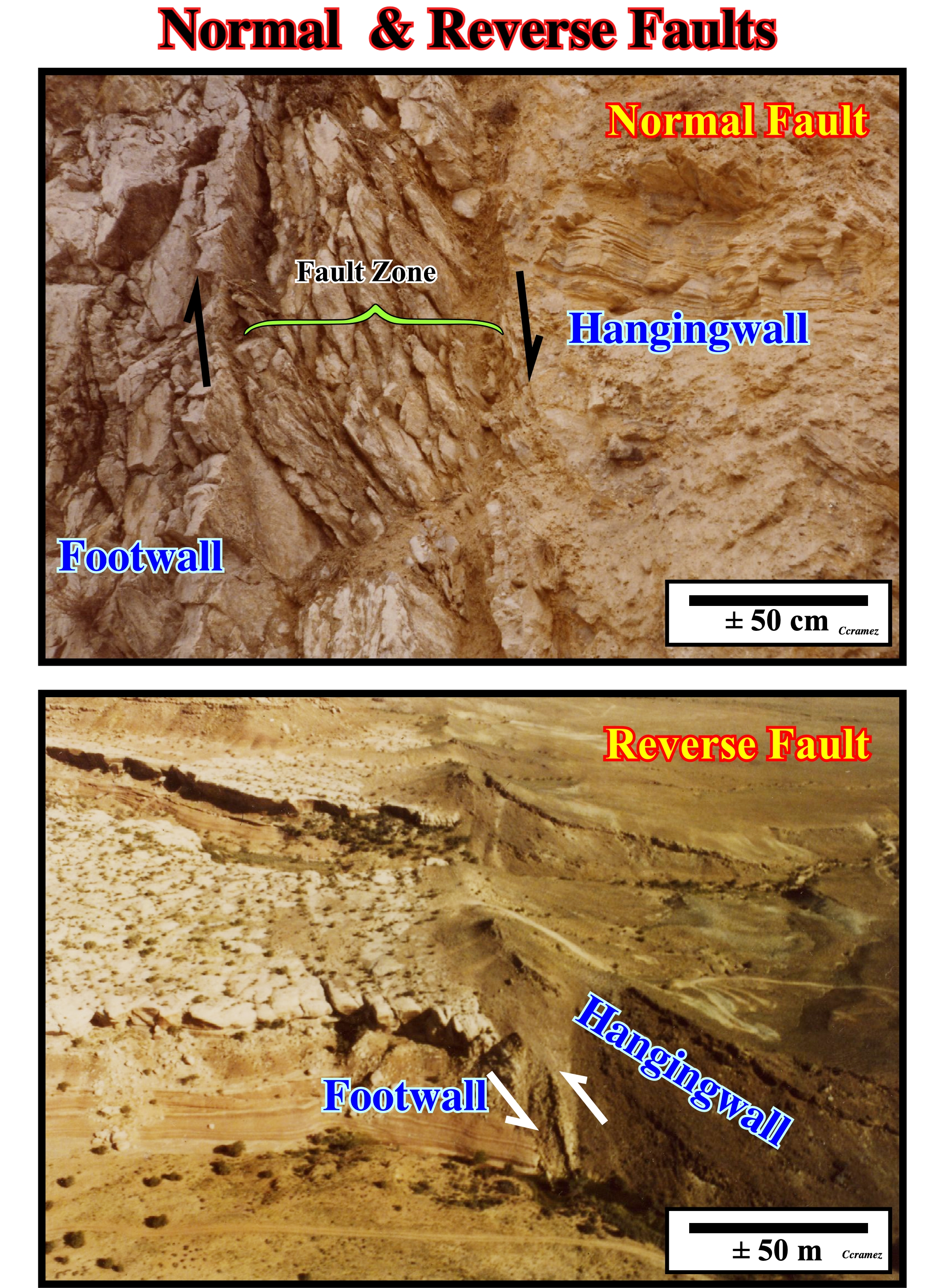
Figure 086- As can be seen on these photos, geologically, a fault is a discontinuity, i.e., a break along which there is a displacement of rocks from one side, relatively, to the other side. However, as illustrated on seismic lines, a fault is not a discontinuity because the wave-front of the reflected wave, generally, does not have terminations, but it is distorted by the fracture zone.
The seismic expression of a fault on a seismic line is the record of the arrivals of a distorted wave-front distorted, accompanied by secondary fronts and shadows. The identification of a fault fault, on seismic lines, requires the recognition of several key elements as (i) Hyperboles (in non-migrated seismic lines) ; (ii) Reflected Refractions ; (iii) Abrupt reflection terminations ; (iv) Dipping seismic surfaces (reflection terminations) ; (v) Dip changes of seismic surfaces, etc.
(i) Hyperboles
Reflections recorded at different receivers constitute hyperbolas on the shot gathers when the traces are sorted in increasing order regarding the channel number or their offset distance. In a reflection hyperbola from a single horizontal reflector model (Derman Dondurur, 2018), the shot point is located at the center of the spread and the recorded hyperbola is symmetrical about the shot location. As a specific case, the reflected signal reaches the receiver first at x = 0 m (the shot location) and the arrival time of the reflected energy at x = 0 m receiver is known as zero-offset time, often designated with t(0) and expressed by t(0)= 2h/V, where h is depth of the reflector and V is velocity of the upperlying medium.
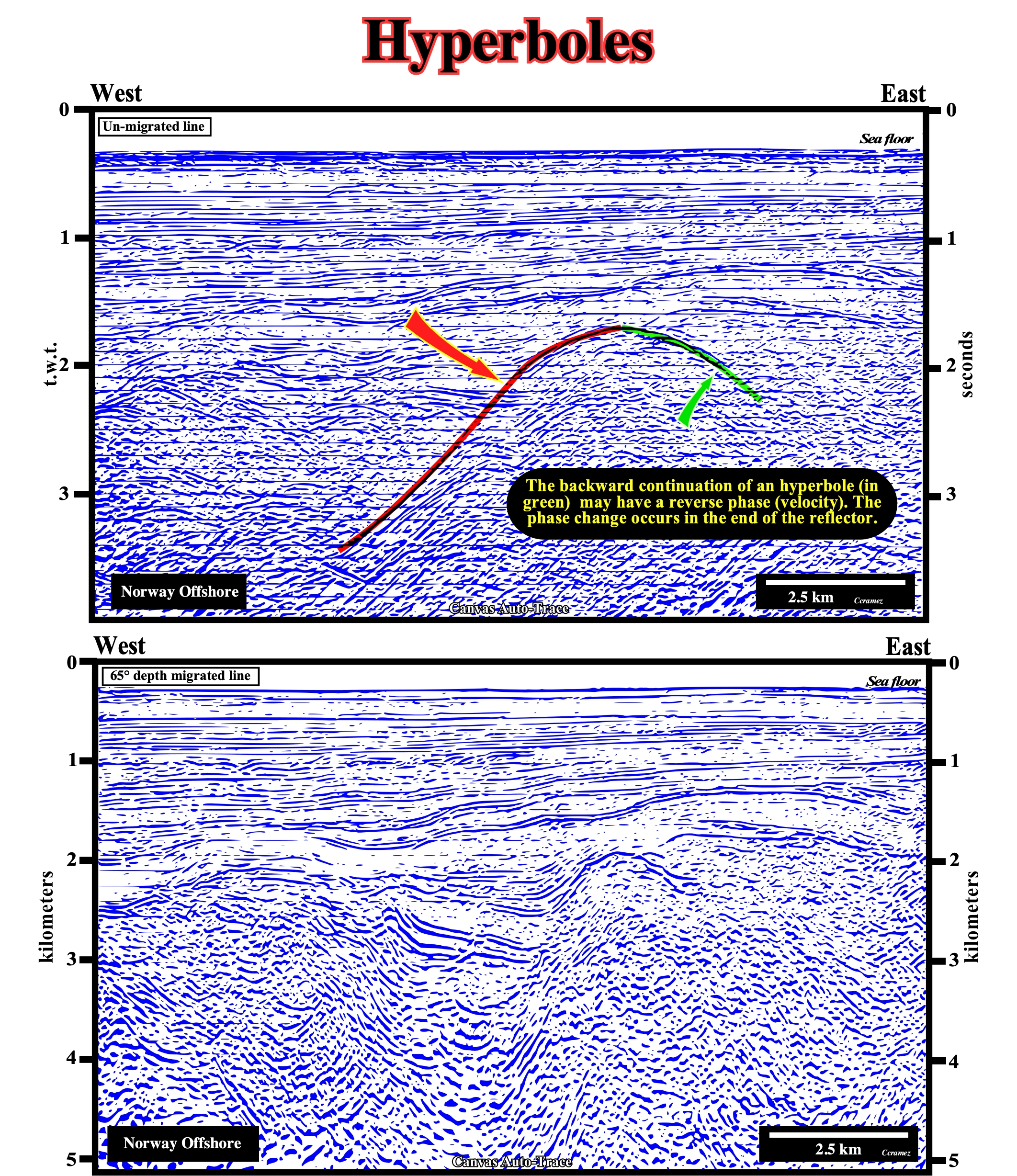
Figure 087- The upper Canvas auto-trace comes from a and un-migrated seismic line* in time (vertical scale in seconds, double time). In the bottom, the Canvas auto-trace comes from a depth-migrated version** of the same seismic line (vertical scale in kilometers). The horizontal scale is the same in both seismic lines. In the un-migrated line, the fault between the two faulted blocks is underlined by a hyperbola of diffraction (in red) and its continuation backward (in green), which, often, can have a reverse phase (function of speed). The phase change occurs at the edge of the reflector. On the depth-migrated version, the hyperbolas disappeared. As can be seen there is no seismic reflector associated with the fault plane, which is recognized just by the reflections terminations of the faulted blocks (hangingwall and footwall).
* Take note the above Canvas are just details of a quite long seismic line, since short seismic lines really are not suited for migration, in which dipping events are moved to their supposedly true subsurface positions, and diffractions are collapsed by migrating the stacked section prior to amplitude scaling.
** Seismic migration is the process by which seismic events are geometrically re-located in either space or time to the location the event occurred in the subsurface rather than the location that it was recorded at the surface, thereby creating a more accurate image of the subsurfac (https://en.wikipedia.org/ wiki/Seismic_migration).
(ii) Reflections Refracted
When the reference point moves away of the fault, the angle of the direct path, in the diffraction point with the reflector falls, eventually, under the critical angle and there will be two arrivals:
1) The first one is the direct arrival, which is a large angle diffraction ;
2) The second is a reflected refraction (refracted in a high-speed layer), which is reflected from the fault plane.The direct arrivals are represented as hyperbolas of diffraction. The reflected refractions are straight arrivals whose slope depends on the velocity in the lower layer and its dip. Clearly, this reflected refraction may appear, just, in the backward direction of the hyperbola. In the front direction of the hyperbola, the refractor does not exist.
In certain sedimentary basins, in order to avoid interpretations of non-existing fault planes, the recognition of the reflected refractions is of paramount importance. The refractions are, often, reflected in rectilinear seismic arrivals. As illustrated below, the slope of a reflected refraction depends on the speed and inclination of the refractor. Any discontinuities in the refractor can be a starting point of a reflected refraction.
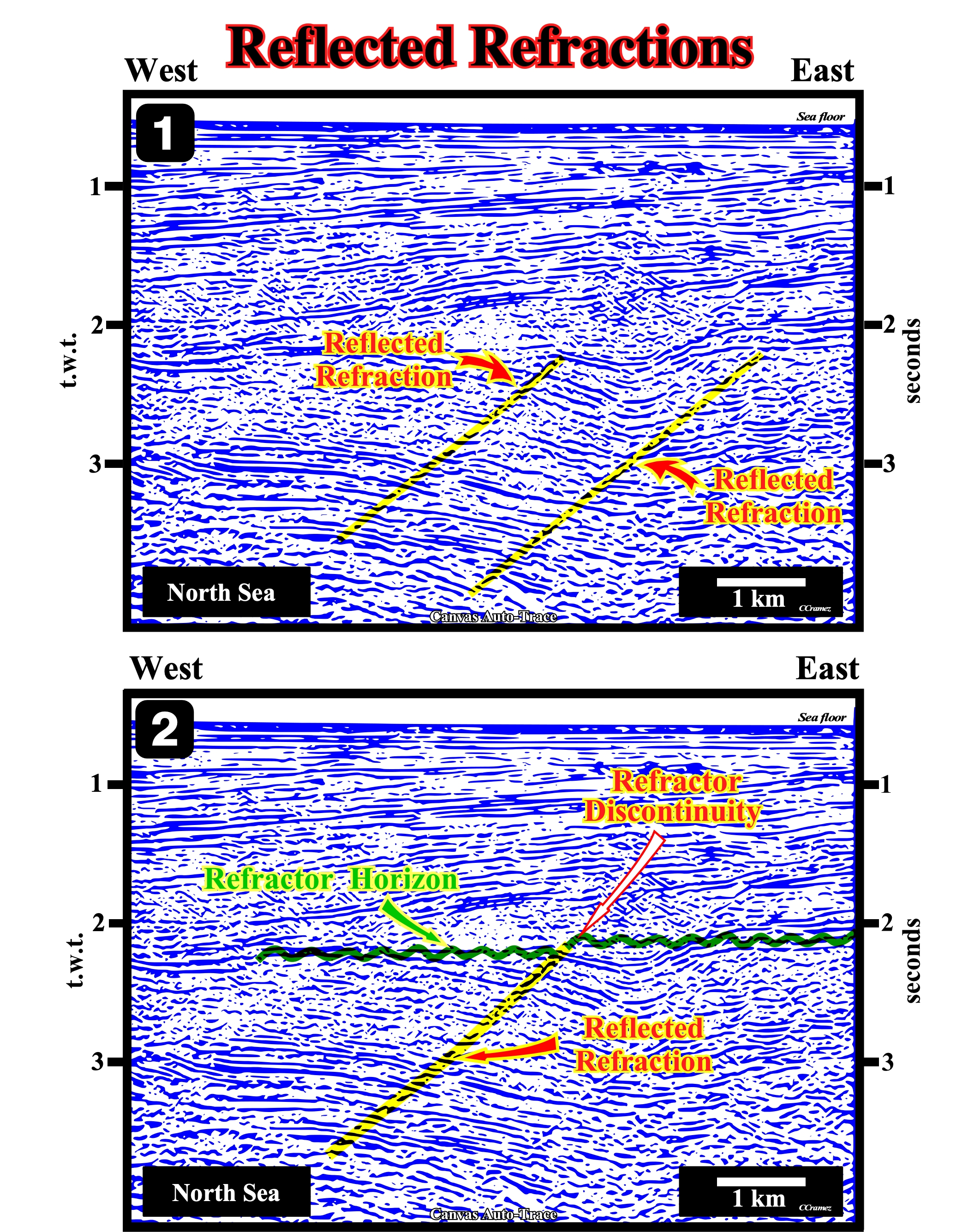
Figure 088- On this detail of a Canvas auto-trace of a North Sea migrated seismic line, reflected refractions are evident in association with a normal fault affecting the refractor horizon, which, in this example, corresponds to an unconformity (erosional surface induced by a relative sea level fall). Generally, on un-migrated seismic lines, a reflected refraction is tangent to the backward hyperbola of diffraction associated with fault. On the front side of the hyperbola, the refractor does not exist at the same level. This explains, probably, why this migrated line, one, just, sees reflected refraction dipping westward. The refractor, colored green, and the discontinuity (vertical displacement of the refractor marker, i.e., a normal fault) creates an obvious reflected refraction. The slope of a reflected refraction (yellow) is function of velocity of the refractor, i.e., the speed of seismic waves along the refractor (green) and its inclination.
A reflected refraction is tangent to the diffraction at a given critical distance. The highest amplitudes are found near the critical distance. Reflected refractions can appear, just, in the backward hyperbola direction. In front, the refractor does not exist. Another seismic arrival of a fault is the single reflection from a fault plane. Therefore, it is necessary that the elastic properties of the two blocks separated by the fault are, sufficiently, different. The reflection associated with the fault can be traced far, just, if the contrast is maintained along the fault. If not, the reflection associated with the fault plane varies so much in magnitude and character that the continuity of reflection will not be maintained.
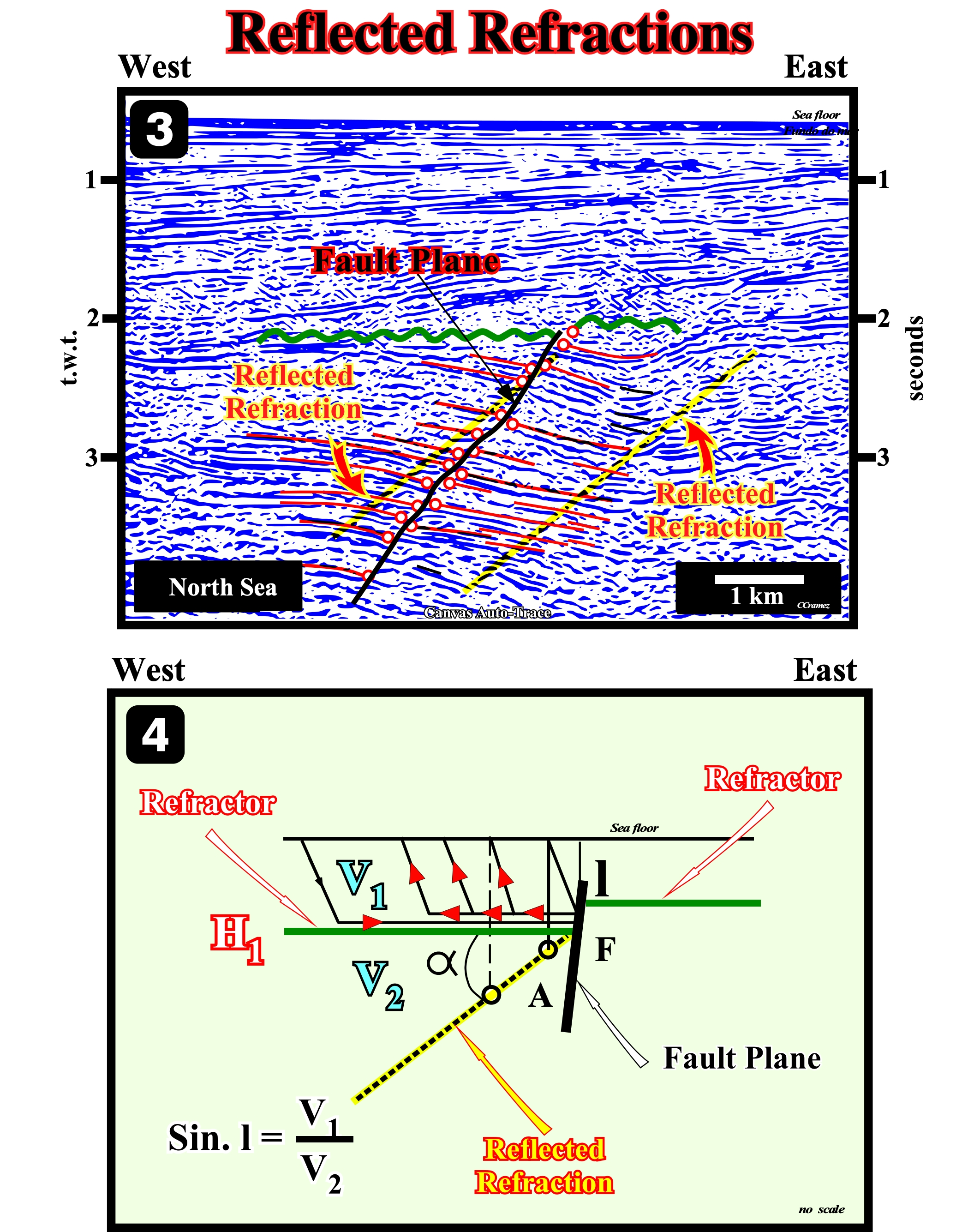
Figure 089- This figure illustrates the differences between a reflected refraction and fault plane of a normal fault that cuts the sediments of a Mesozoic rift-type basin (North Sea). As described above, the reflected refraction (yellow) is rectilinear and dips downward. The slope is function of the speed of compression waves along the refractor horizon. The higher the speed along the refractor horizon (green) is, the greater is the slope of the reflected refraction. The plan of the normal fault (B) is emphasized by the termination of the reflectors (red circles). It displays the slope variations and the hade (angle of a fault plane to the vertical), which increases, slightly, in depth, since the velocity of the compression wave of the sediment increases with depth. The dip changes of the fault plane are induced by the lithological variations in the faulted blocks. The theoretical principle of reflected refractions formation is illustrated in the right sketch. Basically, the seismic waves that reach the refractor horizon (H1 in red) are refracted along it until they find the discontinuity created by the normal fault F. Coming to the point discontinuity (normal fault), the waves are reflected back along the refractor and then up to the receptor. The right diagram shows what happens when a reflector is strong and has a positive reflection coefficient (a low-speed rock covers a rock in which the speed of seismic waves is high). As the viewpoint moves away from the fault, the angle of the direct path between the diffraction point of the reflector, eventually, falls below the critical angle. At this distance, there are two arrivals. The direct one is a wide-angle diffraction. The second is the reflected refraction of rock with high speed, which is reflected from the fault plane. In a seismic line, a reflected refraction appears as a reflection (yellow), more or less continuous and rectilinear dipping downward toward the hangingwall. The dip of a reflected refraction is function of the velocity of seismic waves along the refractor.
(iii) Abrupt Reflection Terminations
Some reflections induced by fault planes are persistent in continuity and regular in character even when they cut a wide thickness of a large variety of sediment. This suggests the fault plane may have lithologic characteristics, which contrast, sharply, with the surrounding rock lithology, in the following instances:
a) When the fault plane is between sediments and basement rocks ;
b) When the fault plane is injected by intrusive rocks ;
c) When the fault zone (gouge) is shaly* and is saturated with water or gas ;
d) When fault plane is filled with sandstone dikes ;
(v) When the fault plane contains mineralized veins ;
(vi) When the fault plane is injected salt, etc.
* The shale of a fault is soft clay, uncemented, sprayed or a clay material, usually, a mixture of finely divided minerals found along some faults or between the walls of a fault, totally or partially filling the fault zone.
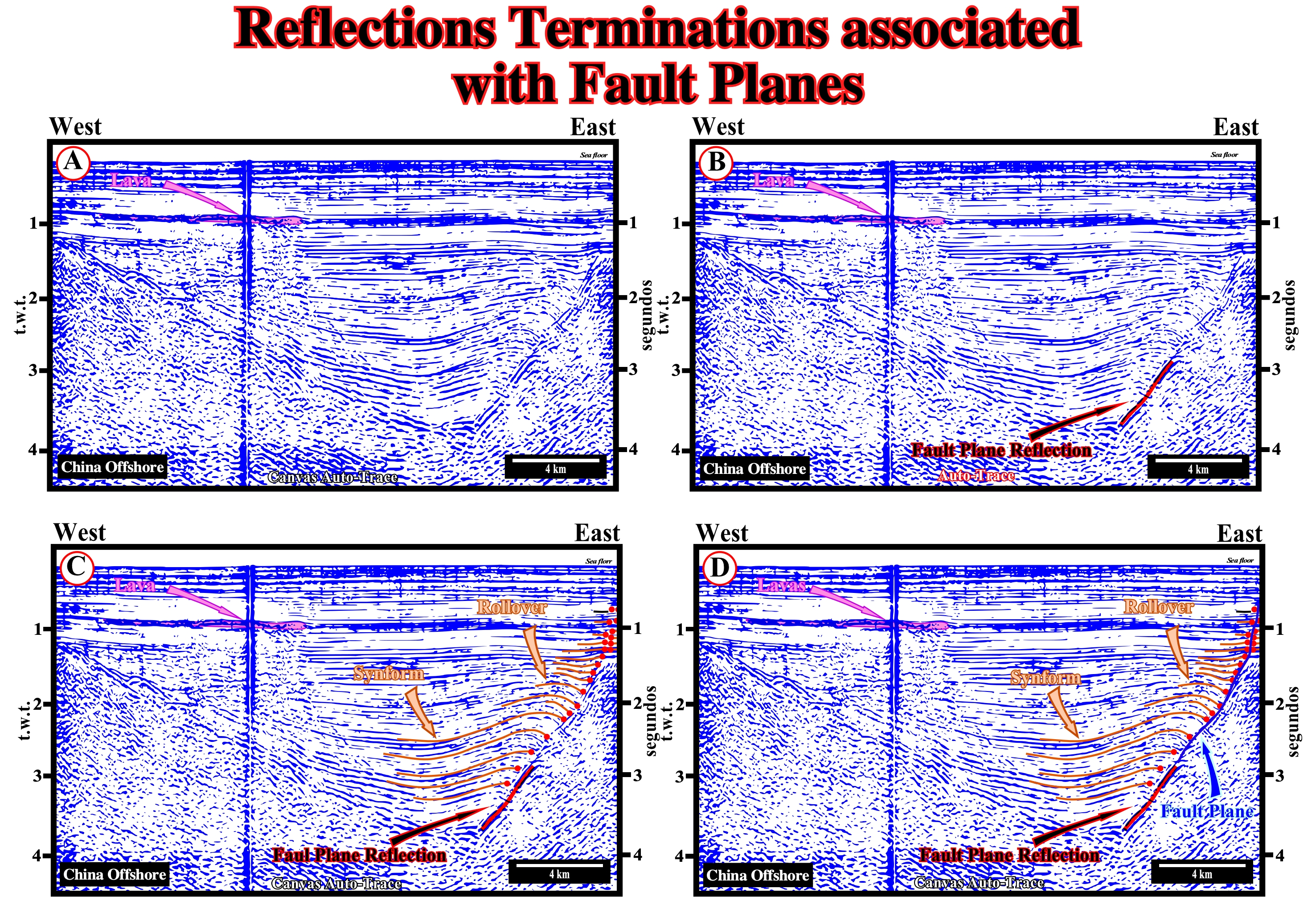
Figure 090- On this Canvas auto-trace of China offshore seismic line, a rift-type basin type-rift, of the rifting phase of back-arc basin underlying the burial phase, is obvious. The boundary between these two phases of a back-arc basin is, in western sector, reinforced by the presence of a lava flow, which deteriorates, substantially, the underlying reflectors. The plan of the normal fault (slightly reactivated in reverse fault) bordering the half-graben of the rift-type basin, is underlined by a strong amplitude reflection in the lower sector of the fault plane. The median and upper section of the fault plane have no associated reflections. The picking and the reflector terminations within the rift-type basin is very clear, as can be seen in tentative to interpretation (C), in which a rollover and a synform are discernible. The geometry of the fault plane in the median and upper sectors is determined, easily, from the eastern reflector terminations of the rift-type basin, as illustrated in the tentative D (continuous blue line). The change of dips in the fault fault causes the formation of a rollover and a synform. The sediment were lengthened, probably, by small normal faults with throws under the seismic resolution, since the sediments have to fill the space created by the compaction, which induces changes in dip of the fault plane. The dip changes of the fault plane are, probably, caused by lithological changes in the footwall. In the footwall, the area below the dip change corresponds, probably, to Precambrian granitic rocks, while the area above corresponds to Paleozoic sedimentary rocks.
A seismic arrival induced by a fault is nothing more than the reflection of the fault plane. However, for this to happen, it is necessary that the elastic properties of rocks separated by the fault plane are, sufficiently, contrasted, as for instance, when the fault plane separates shale-sand sediments from a salt interval or from the basement. The reflections associated with a fault plane can also be induced by a mineralization of the fault zone or the intrusion of igneous rocks in the fault zone.
The occurrence of a reflection associated with a fault plane depends, also, on the fault geometry, particularly, its dip. Generally, the fault planes very inclined, even with strong impedance contrast of juxtaposed rocks, are not emphasized by reflections. A fault plane can, easily, be determined by the space between the reflections terminations within the faulted blocks.
(iv) Dipping Seismic Surfaces (reflection terminations)
Under normal geological conditions, there is no primary seismic reflections associated with the fault planes. In practice, the picking of a fault plane on a seismic line, obeys certain rules of interpretation, since a fault corresponds to a discontinuity, more or less, abrupt the sedimentary layers along which there was an appreciable displacement.
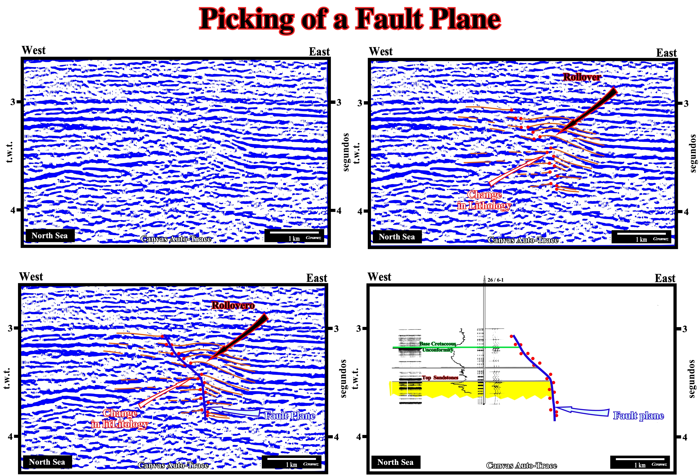
Figure 091- On this figure are illustrated two examples of North Sea. In the first one (top), the terminations of the reflectors of the faulted blocks (see, below, the detailed picking of the fault plane) show, clearly, the dip variations of the fault plane and a rollover (accommodation fold) in the reflectors of the hangingwall, suggesting a lateral change in lithology between the faulted blocks. In the example at the bottom, which is calibrated by the results of an exploration well, the fault plane following the reflectors terminations (red dots) shows, also, a change in the dip of the fault plane and a rollover in the hangingwall (which descends relative to the footwall). The calibration of seismic line of this Canvas auto-trace shows, in relation to the footwall, that the fault plane is more upright when it crosses sands than when it crosses shales (see later).
The first step to pick a fault is the location of the reflection terminations of the reflectors which emphasize the geometry of the fault plane. As shown previously, the geometry of a fault plane, in the field or on a seismic line, in general, is not rectilinear :
- The dip of a fault plane changes along the fault plane function of the rheological behavior and compaction of sedimentary layers ;
- The irregular geometry of the fault planes contrasts with the rectilinear geometry of reflected refractions, whose dips underline the velocity of the waves along the refractor horizon ;
- Reflected refractions and fault planes, often, appear next each other, as it is the case on North Sea seismic line illustrated above ;
- As a seismic line is a time section, it is, physically, impossible that a fault reverse or normal, exhibits a rectilinear geometry.
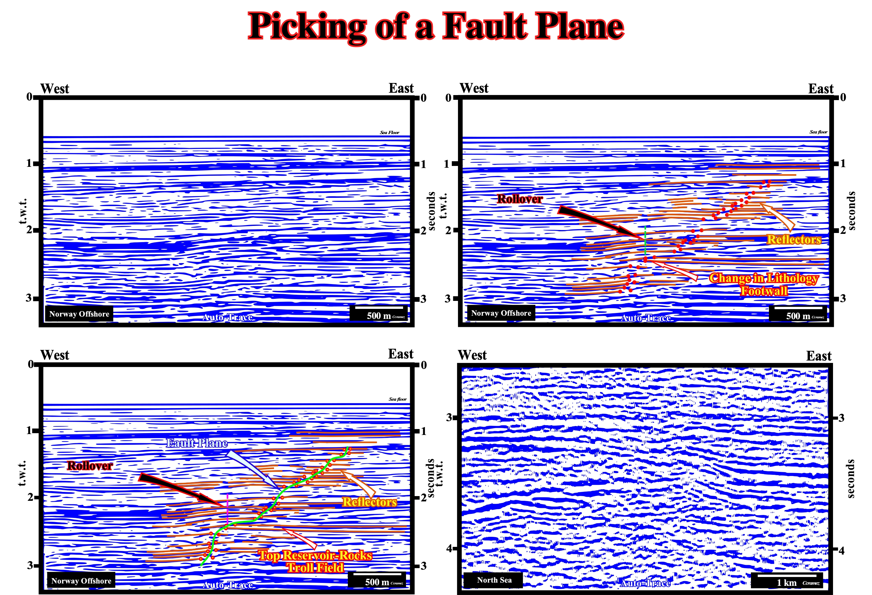
Figure 092- On this figure is illustrated the picking of a fault plane in Canvas auto-traces of Norway offshore seismic line (top lines and bottom line left). The clean auto-trace is shown in the upper left corner. In the at the top right auto-trace, the geoscientist picked, i.e. followed with a pencil or a computer mouse, several reflectors in each faulted block and put a red dot on the reflector terminations that define the fault. Next, as shown in the lower seismic line (left), he picked the most likely fault plane by drawing a line (blue) between the reflector terminations (between the dots). Several dip changes of the blue line and rollovers (in the hangingwall) are visible. They represent juxtapositions of different lithologies along the fault plane. As an exercise, try to purpose a tentative geological interpretation geological of the line on the bottom right corner, without forgetting the picking of the fault plane.
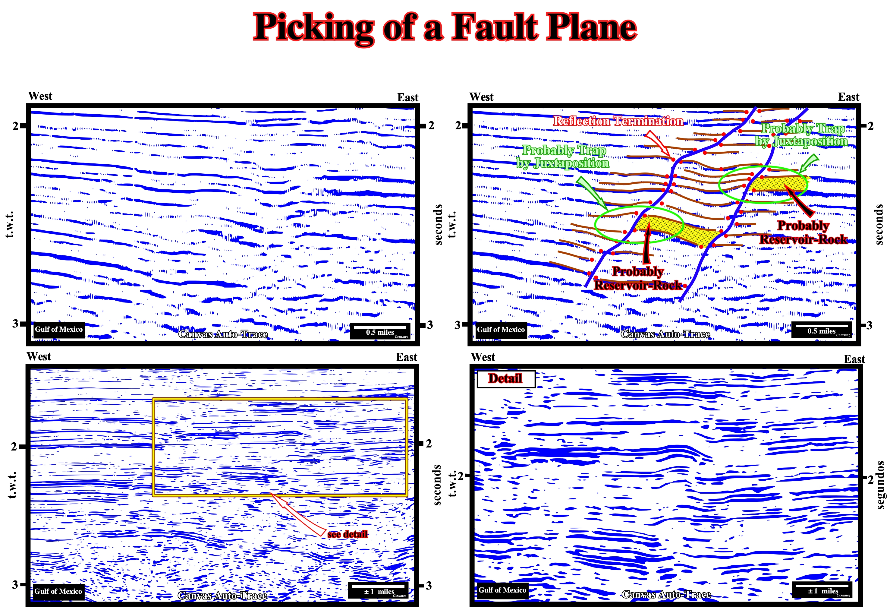
Figure 093- Above is shown a clean Canvas auto-trace of a Gulf of Mexico seismic line and a tentative interpretation of the fault planes, as well as the location of two intervals with reservoir-rocks, although there are others. The lower seismic lines, particularly the line on the left (at the right is a detail) illustrate the absence of reflectors associated with the fault planes. Propose a tentative interpretation the fault planes in the detail of the line, indicating the more likely morphological trap by juxtaposition and locating the potential reservoir and sealing-rock.
(v) Dip Changes on Seismic Surfaces
In the field, as on the seismic lines, the dip of the fault planes of normal faults, predating the compaction of the sediments, is, rarely, constant. Just the very recent faults, postdating the compaction of the sediments, have a rectilinear fault plane with a constant dip.
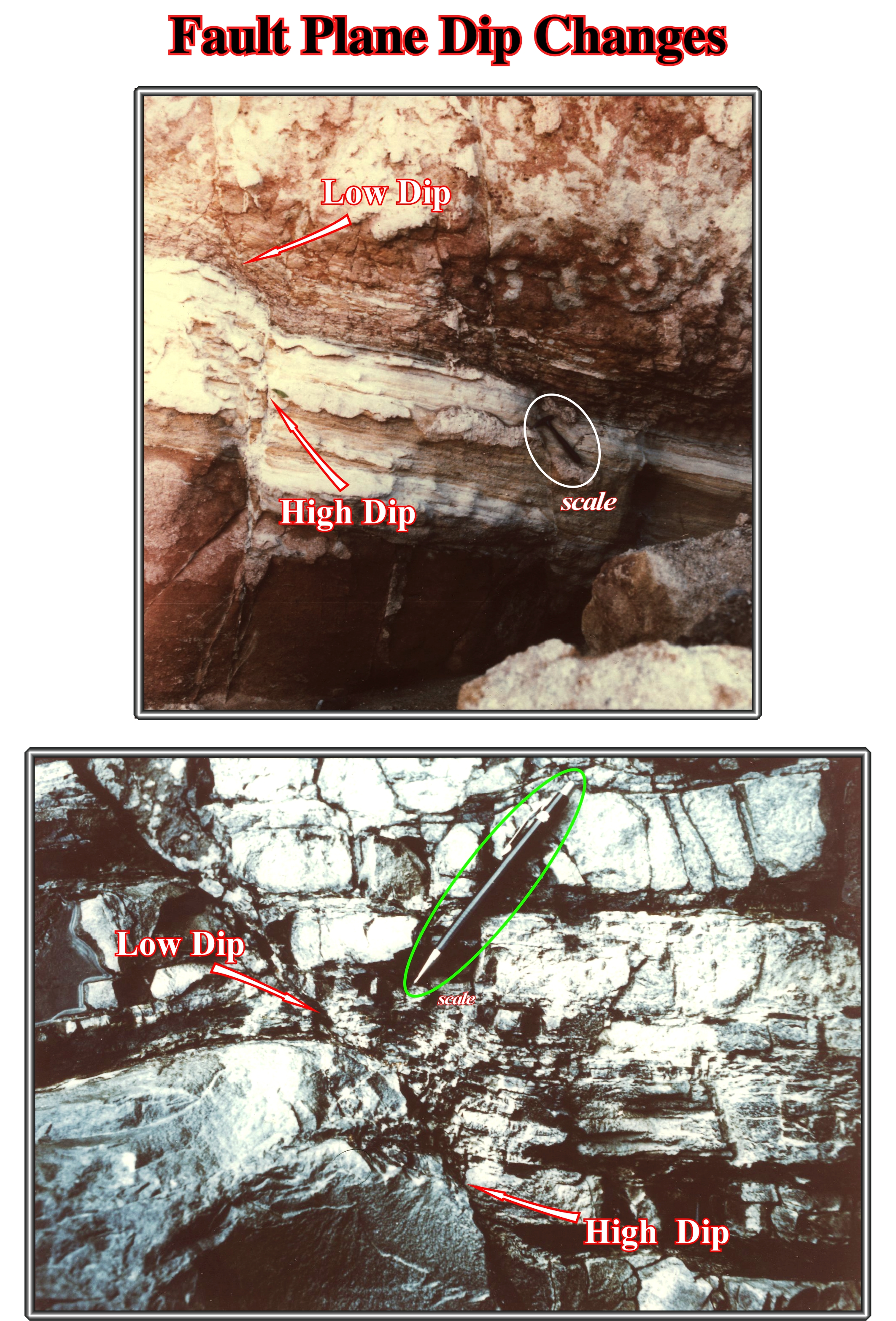
Figure 094- In these photographs, at the mesoscopic scale (scale of the continuity), the fault plane is more inclined (closer to vertical) when the fault crosses sediments less compactable, such as carbonates and sandstones. In shaly intervals, which are more compactable, the dip of the fault planes is smaller, i.e., the fault plane tends to flattens out. In upper photo (alternation of clean sandstones, in white color, and shaly-sandstone, in pink color) the dip of the fault plane is greater in clean sandstones. In the lower figure, the dip of fault plane is greater in compact limestones than in the argilaceous limestones. This geometry is observed, also, in drilling cores. All geoscientist working in the petroleum exploration knows that the dip of the fault planes and fractures is higher in reservoir-rocks than in the sealing rocks.
A simple explanation of the fault plane geometry can be proposed taking into account the rheological characteristics, the volume problems (Goguel's law) and the compaction effects in the different sedimentary layers.
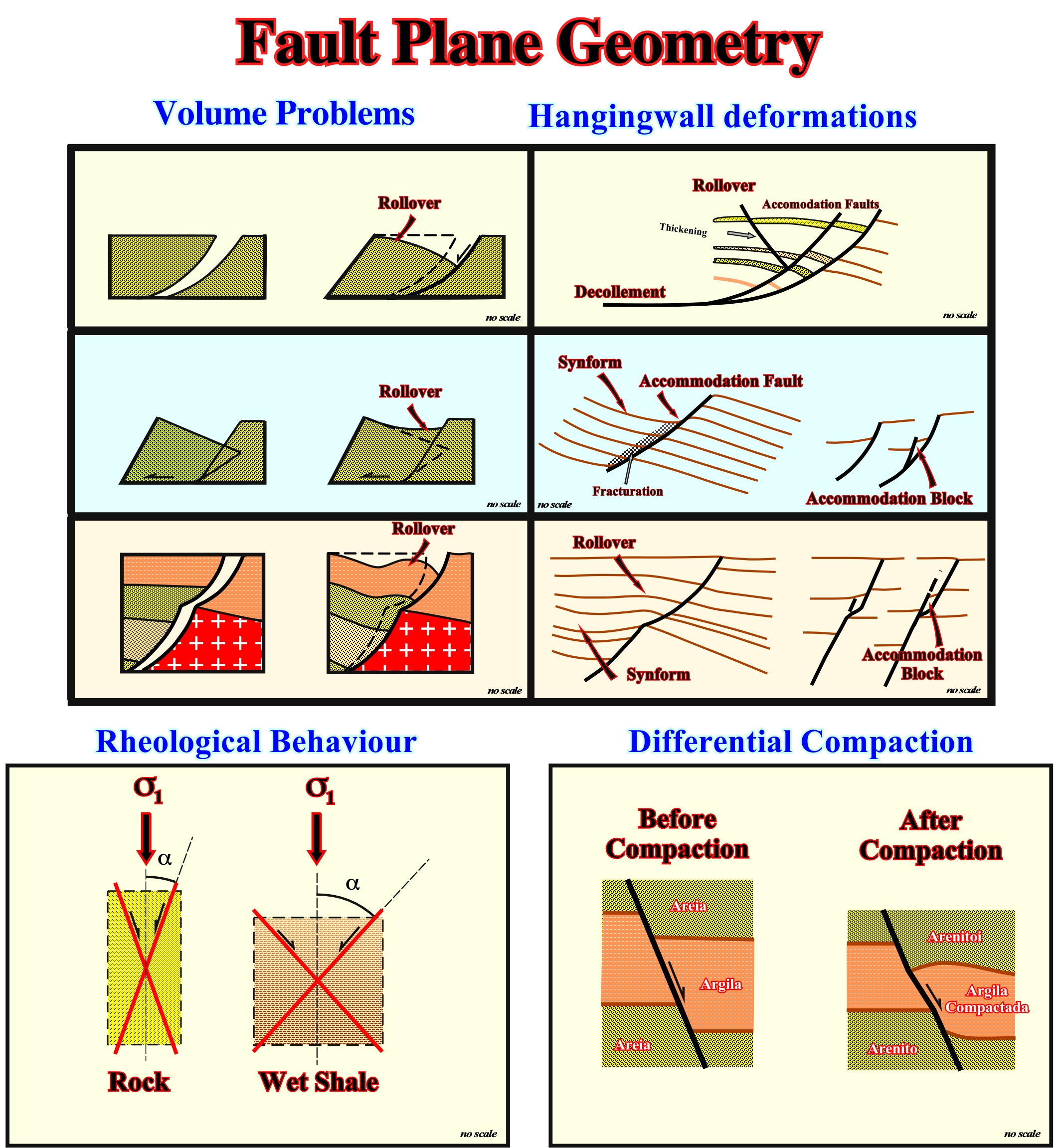
Figure 095- Theoretically, it can be said that dip variations of a fault plane of a normal fault is due to a volume of problem, which can be induced either by lengthening of the sediment or by a differential compaction, or by a combination of these two geological phenomena. When a homogeneous sedimentary interval (with the same lithology), bounded at the base by a detachment surface or decollement, is subjected to an extensional tectonic regime (σ1 vertical), it is lengthened by normal faults (parallel to σ2) ending on the detachment surface. The sliding of the upper faulted blocks (hangingwalls) along the detachment surface creates a volume problem. Depending on geological conditions, there is formation or reduction of available volume for the sediments. Thus, to respect the Goguel's conjecture that during the deformation, the amount of sediment is, more or less, constant, the sediments are forced to deform in order to accommodate the new volume conditions. If there is excess of volume, the sediment will be deformed in antiforms (accommodation folds). If there is no volume enough, the sediments be deformed in synforms. When a heterogeneous sedimentary interval, formed by different facies, is subjected to an extensional tectonic regime (σ1 vertical), it is elongated by normal faults (parallel to σ2). However, as each facies has a characteristic rheology, the dip of the fault plane changes, and so the space created between the two faulted blocks, as shown in the upper diagrams. On the other hand, as the nature abhors empty, the sediments have to length to fill the volume created by extension. In an heterogeneous elongated sedimentary interval, even if, locally, there is no creation of volume (where the dip of the fault plane is 90°), the compaction of the sediments creates volume problems that change the dip of the fault plane. If sand-shale interval, the original dip of the fault plane is, roughly, 75°, as the compaction of the shale levels is much higher than that of the sand levels, the dip of the fault plane becomes, e.g., 70 ° in front of the sands of the footwall and 50-55° in front of the shale horizons, which requires, obviously, a deformation of the strata.
Not only field examples of the deformation of fault plane geometry have been described almost in all sedimentary basins, but on the tentative geological interpretation of the seismic lines as well.
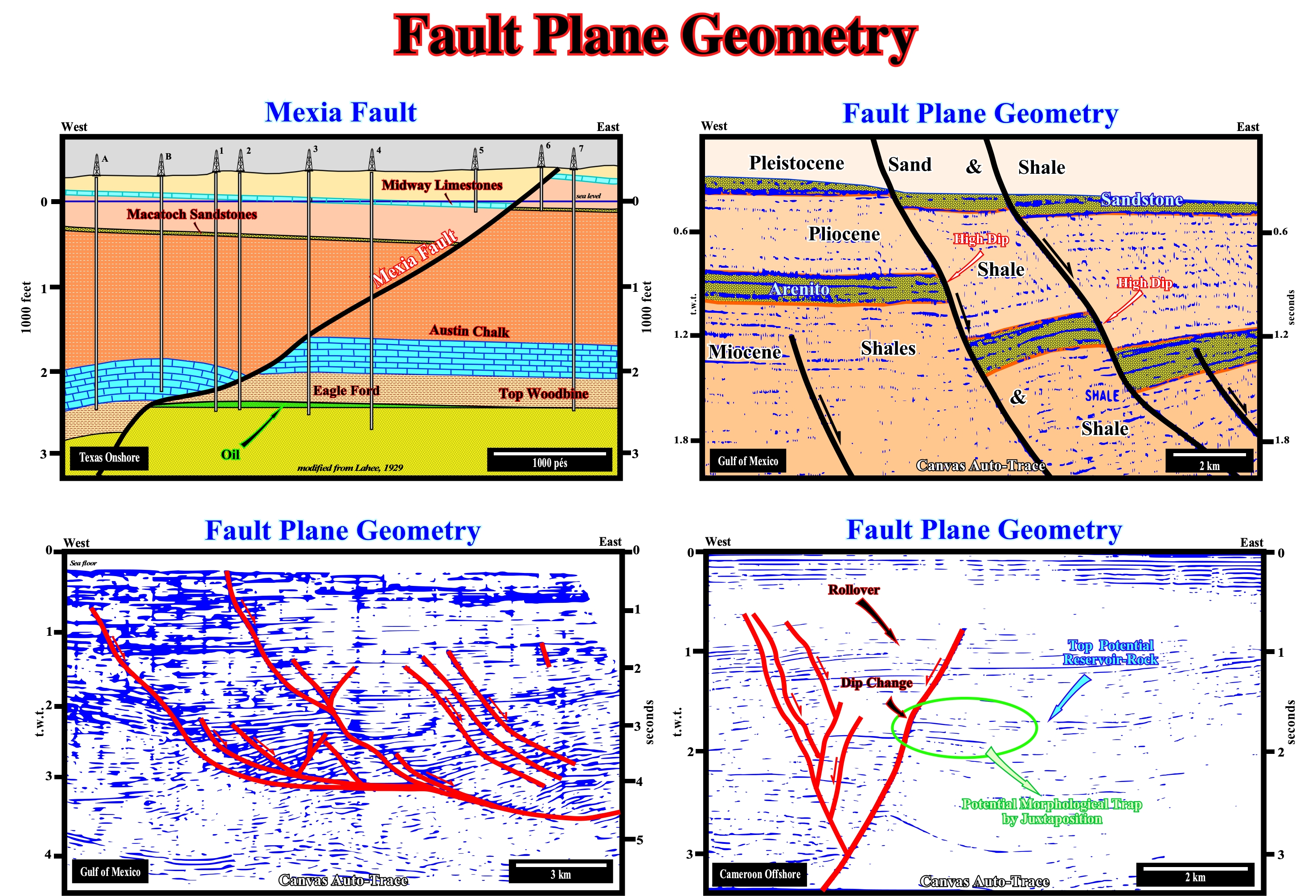
Figure 096- In these examples, it is easy to see in morphological traps by juxtaposing, the dip of the fault plane is higher in front of reservoir-rocks (footwall). The lateral closure area depends on the thickness of the reservoir-rock and on thickness of the sealing-rock juxtaposed to the reservoir-rock. Also, as illustrated on the Canvas auto-traces of the Gulf of Mexico seismic lines, all normal faults flattened in depth. Normal faults are curved, even when they affect the basement. It is important do not forget that there are no vertical normal faults. A normal fault is formed to length the sediments. A vertical normal fault does not length or short the sediments. To have lengthening is necessary to have available space. A vertical normal failure would implicate available space within the crust, which does not exist. When a fault plane is vertical (in depth), it is, necessarily, a strike-slip fault (in compression or in extension). Naturally, these conjectures are much more evident on seismic lines (macroscopic scale) than the field (mesoscopic scale). Furthermore, on seismic data (vertical scale in time), even sectors where a normal fault is, more or less, vertical,on a seismic line, it is curved and flattens in depth, since on seismic data the interval velocity increases, always, in depth.
(v) Dip Changes on Seismic Surfaces
On a seismic line, a fault corresponds to a break in the continuity of the seismic reflectors interpreted as chronostratigraphic lines, i.e. as sedimentary intervals, more or less, thick (depending on the seismic resolution). Rarely, a fault plane (interval between the faulted blocks) is underlined by a reflector (impedance contrast), except in three specific cases : a) When the fault plane is injected salt or volcanic material ; b) When the acoustic impedance contrast between the faulted blocks is very strong, such as when a fault block has a granite-gneiss facies ; c) When the fault zone is thick and with a facies different of the faulted blocks.
On seismic lines even the faults postdating compaction are concave (upward), since the interval velocity increases in depth. On other words, even a straight fault plane on the ground appears on a seismic line curvilinear in depth. On this subject it is important do not forget that when a fault exhibits a vertical fault plane, it is necessarily a strike-slip fault (in extension or compression), since a normal fault can never have a fault plane vertically. A normal fault is formed to length the sediments (figure 097). A fault with a vertical fault plane lengthens or shortens the sediments. Moreover, in depth, except in rare cases locations (caves, for example), there is no free space (nature abhors the void), which prevents the formation of a normal fault with a vertical fault plane on a macroscopic scale. When a fault predate compaction, the dip of the fault plane, even if it was straight to the moment of rupture, it is then deformed due to the different compaction of sedimentary intervals. In more compressible intervals, i.e. those in which the thickness is further reduced by compaction, and in clays, the dip fault plane, of course, is smaller (the fault plane becomes more horizontal). Unlike, in sedimentary intervals less compressible (compactable) such as sandstones and limestones, the original dip fault plane is less deformed, that is to say, less reduced.
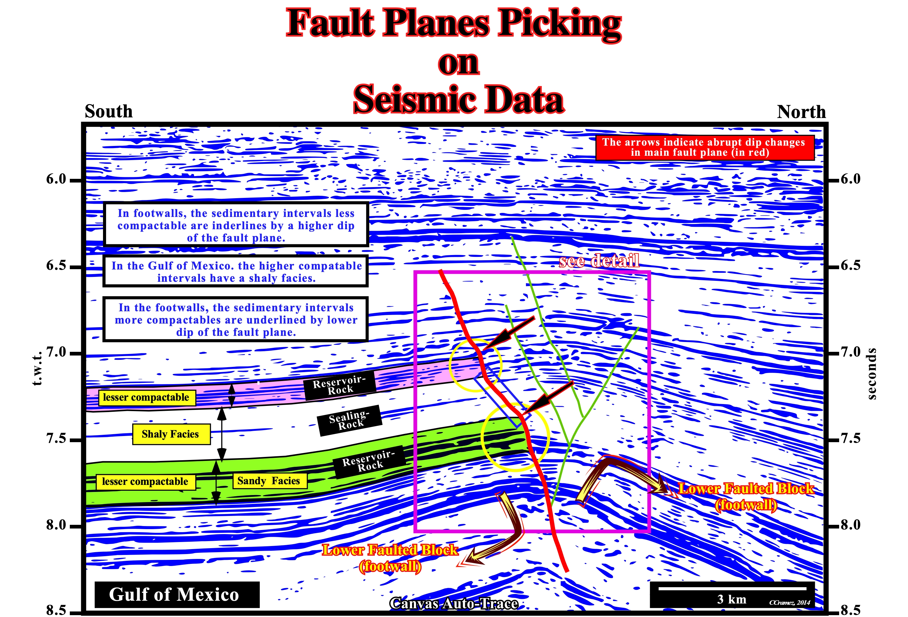
Figure 097- As illustrated in this tentative geological interpretation of a Gulf of Mexico offshore seismic line, at the scale of macroscopic observations (scale of geological maps and seismic lines) there are no straight rectilinear) fault planes. This is particularly true, especially, when faults predate compaction (process whereby the porosity of a given sedimentary interval is decreased once its mineral grains are squashed by the weight of overlying sediments or mechanical means).
On seismic lines even the faults postdating compaction are concave (upward), since the interval velocity increases in depth. On other words, even a straight fault plane on the ground appears on a seismic line curvilinear in depth. On this subject it is important do not forget that when a fault exhibits a vertical fault plane, it is necessarily a strike-slip fault (in extension or compression), since a normal fault can never have a fault plane vertically. A normal fault is formed to length the sediments. A fault with a vertical fault plane lengthens or shortens the sediments. Moreover, in depth, except in rare cases locations (caves, for example), there is no free space (nature abhors the void), which prevents the formation of a normal fault with a vertical fault plane on a macroscopic scale. When a fault predates compaction, the dip of the fault plane, even if it was straight to the moment of rupture, it is then deformed due to the different compaction of sedimentary intervals (Figure 098). In more compressible intervals, i.e. those in which the thickness is further reduced by compaction, and in clays, the dip fault plane, of course, is smaller (the fault plane becomes more horizontal). Unlike, in sedimentary intervals less compressible (compactable) such as sandstones and limestones, the original dip fault plane is less deformed, that is to say, less reduced.
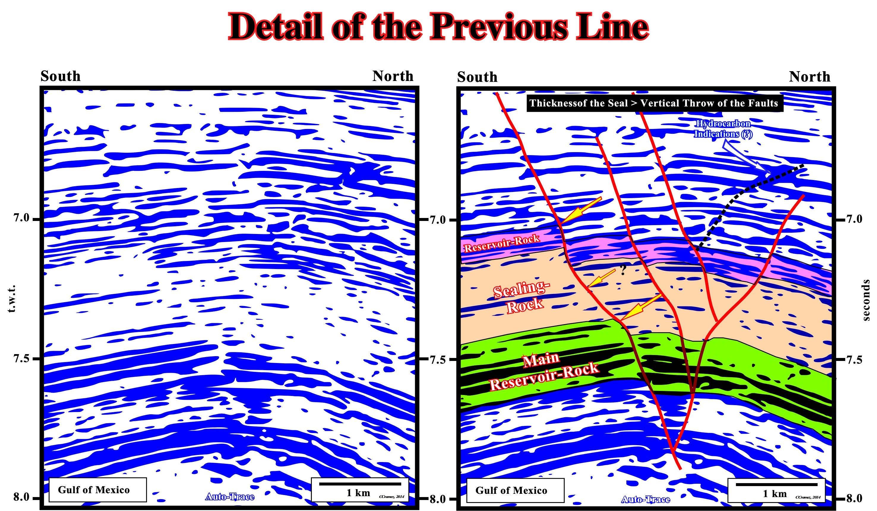
Figure 098- The detail of the seismic line illustrated in the figure above shows, clearly, what many geoscientists, responsible for tentative geological interpretation of seismic lines, forget : the fault plane is a mental construction of observers based on the abrupt interruption of chronostratigraphic lines, which of course prevents an automatic picking. On the other hand, it is obvious that there is no seismic reflector associated with the fault planes (potential hydrocarbon indications along a fault plane are visible), which of course, prevent an empirical picking (based in simple observations, not methodical or rationally interpreted). A rational picking of fault planes shows, as illustrated on next tentative interpretations, major lithological informations, particularly, in shale-sandstones intervals, in which reservoir- and sealing-rocks can be easily identified in footwalls (lower faulted blocks).
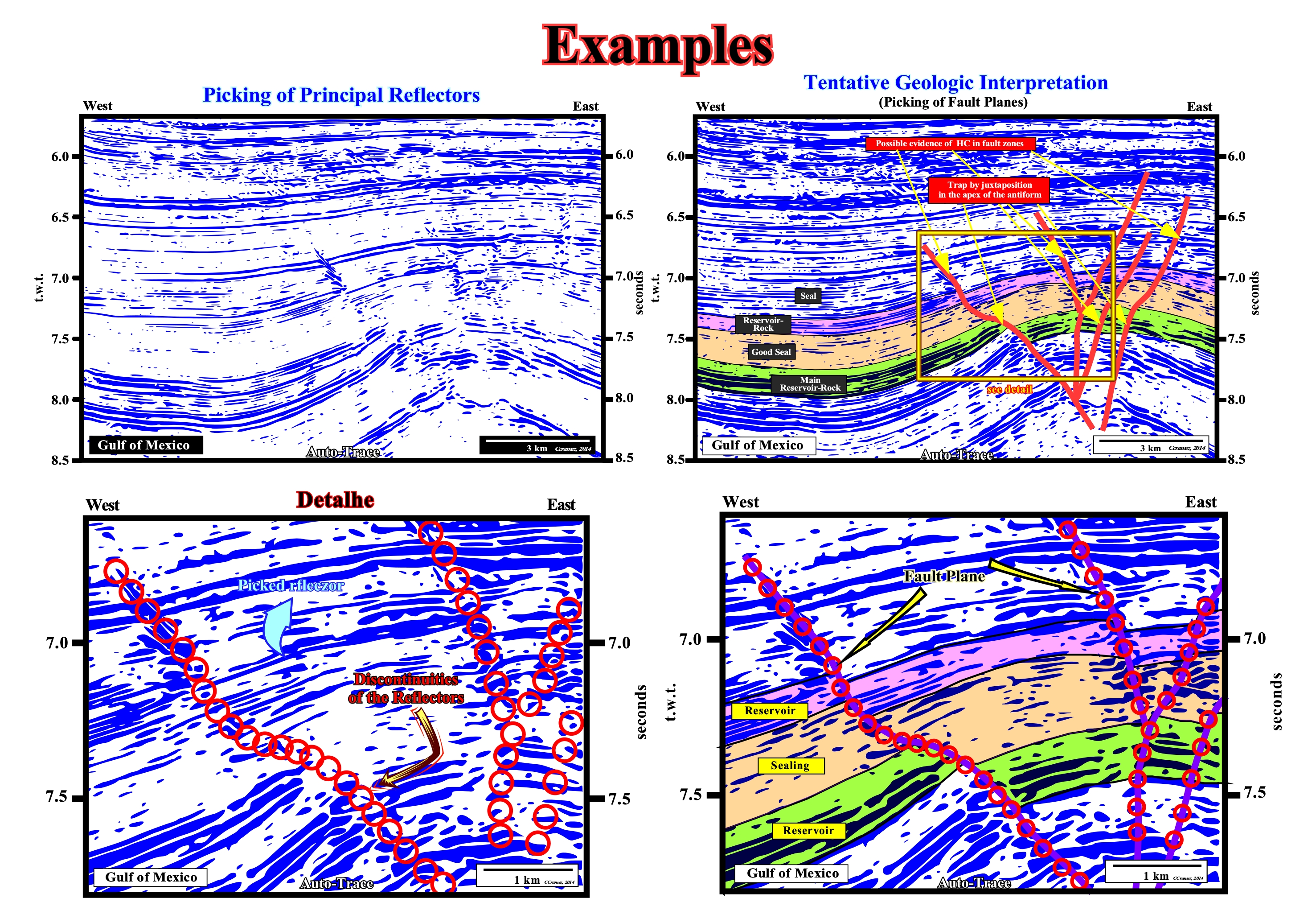
Figure 099- The likely presence of hydrocarbons in the fault planes is supported by the amplitude anomalies visible on these seismic lines. The rational picking of fault planes is, undoubtedly, the locus (set of points or space that have the same property) of the terminations reflectors of the two faulted blocks. The dip changes of fault planes are obvious. They emphasize lateral variations of the lithology (different compactions) between the faulted blocks and show potential non-structural traps (morphological by juxtaposition).
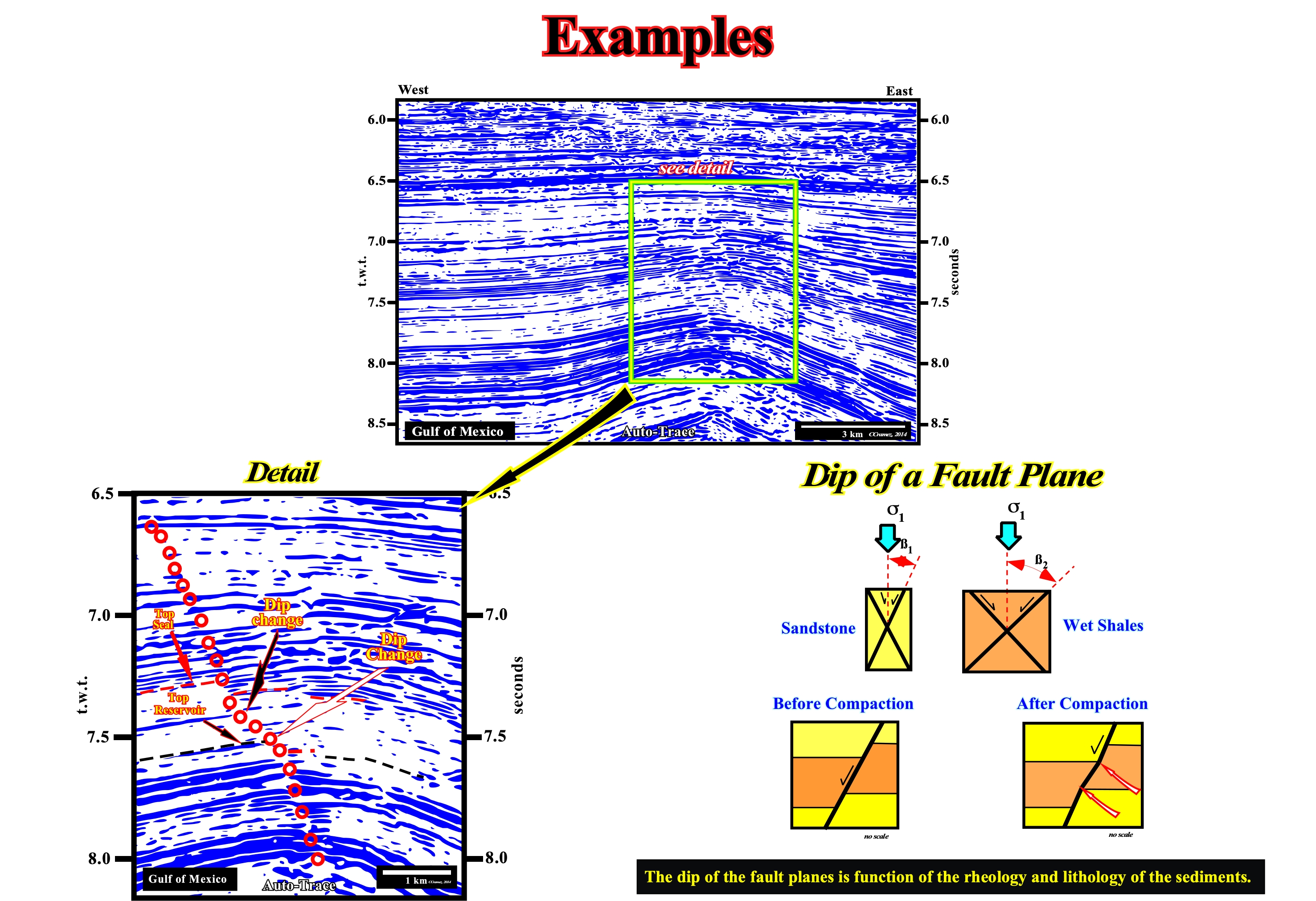
Figure 100- The picking of the fault plane illustrated in the detail is, probably, the less falsifiable and the one which gives more information not only on the lithology of the faulted blocks, but, as well as, on the most likely location of the morphological traps by juxtaposition. The geological process responsible of dip variations of a fault plane is illustrated in the right sketch.