
Caveat:
These notes should not be taken as an attempt to write a textbook on Turbidite Deposits. They are just an eclectic assemblage of geological models, cross-sections and seismic profiles used during my work sessions. Some of the plates were taken from scientific publications and University's courses (Peter Vail at (ice University, Texas, USA ; Emiliano Mutti at Parma University), who I would like to thanks for their teaching and allowing me us to utilize some of their ideas. For confidential reasons, some of the seismic lines are illustrated just by geological tentative interpretation (the clean seismic lines will be shown during the working session).The majority of the data can be used without authorization. In case of doubt, please contact me (carlos.cramez@bluewin.ch or carloscramez@gmail.com).
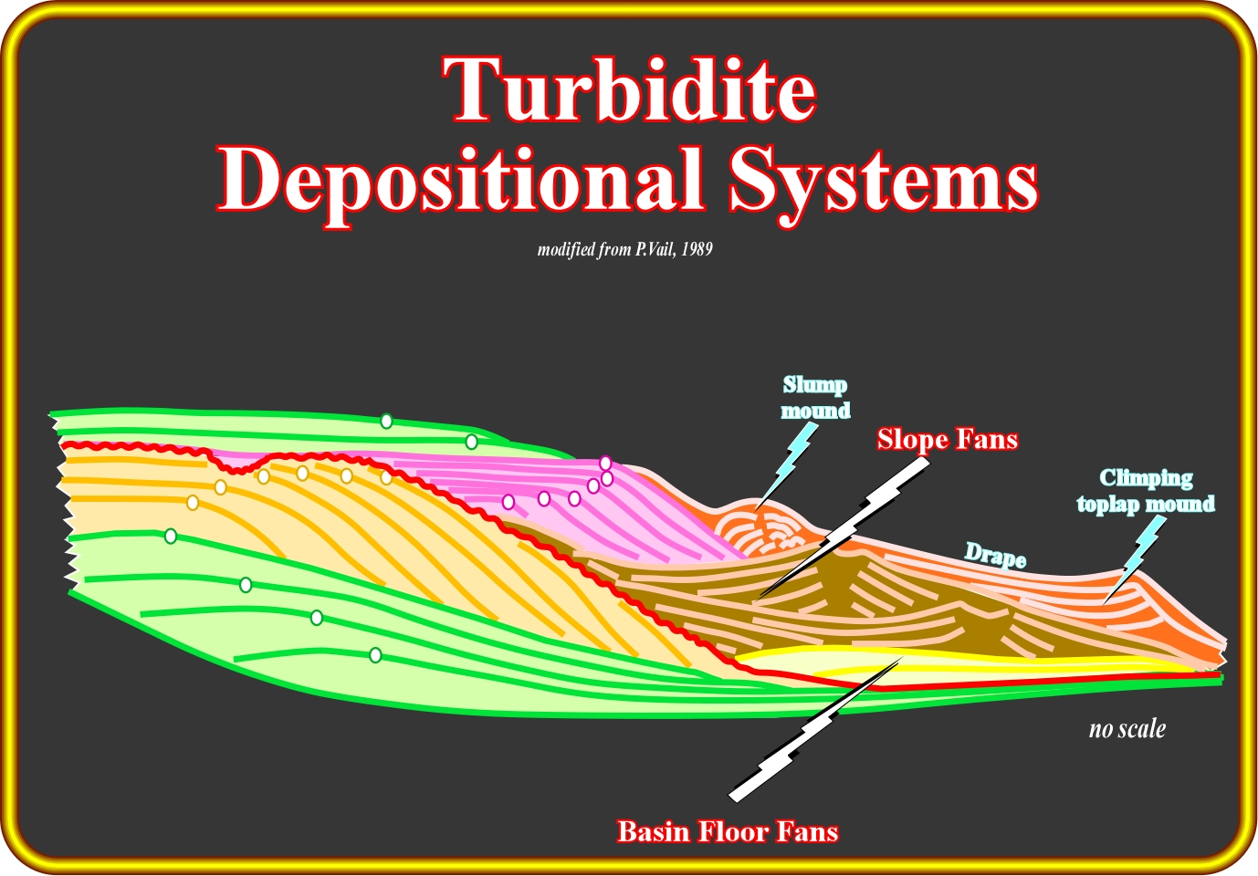
Several geological models have been invoked to explain marine turbidite depositional systems. On these notes will focus on Vail and Mutti turbidite models, as well as, on the upwelling submarine erosion model. They, are, by far, the most useful in petroleum exploration. The Vail's model is schematised on this plate, where two incomplete stratigraphic sequence-cycles are separated by an unconformity (in red), which corresponds to an erosional surface (take into account the incised valley) induced by a significant relative sea level fall. The lower sequence-cycle is represented by the highstand systems tracts (transgressive systems tract or transgressive interval, in green, and highstand systems tract, in beige). The position of the successive shelf breaks (underlined by white circles) depicts the retrogradational geometry of the transgressive systems tract and the forestepping or progradational geometry of the highstand systems tract. The upper sequence-cycle is, mainly, represented by the lowstand systems tract (below the upper transgressive systems tract, in green), in which three members can be recognized. From bottom to top, they are : (i) Submarine basin floor fan ; (ii) Submarine slope fan and (iii) Lowstand prograding wedge, which, seaward of the shelf break, is, often, fossilized by pelagic shales and slumping mounds. The submarine basin floor and slope fans are turbidite deposits induced by gravity current developed in association with significant relative sea level fall (according to P. Vail), which exhuming the shelf of the previous sequence-cycle, strongly, increases the terrigeneous influx.
Turbidite deposits (geoscientists call them turbidites) are induced by turbiditic currents, which can be defined as currents of sediment-laden water moving down a slope (continental or deltaic) through water or another fluid. A turbiditic current moves because it has a higher density than the fluid through which it flows. The driving force of a turbiditic current derives from its sediment charge, which renders the turbid water denser than the clear water above. Turbidity currents are an example of density or gravity currents, which include : (i) Oceanic fronts (boundaries between distinct water masses having different temperatures, salinities, or densities, which move in different directions) ; (ii) Avalanches or rock-slides (landslide caused by rock failure, in which part of the plane of failure passes through intact rock and where material collapses in mass and not in individual blocks) ; (iii) Lahars (mud-flow or debris flow composed of a slurry of pyroclastic material, rocky debris, and water) ; (iv) Pyroclastic flows (fast-moving current of hot gas and rock (collectively known as tephra), and (v) Lava flows (streams of molten rock that pour or ooze from an erupting vent).
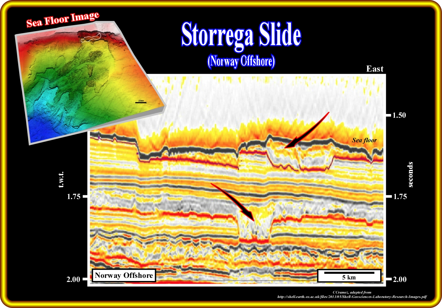
As illustrated on this plate, not all turbidite deposits can be explained by the Vail's turbidite model, in which significant relative sea level falls not only create lowstand geological situation but put in motion turbiditic currents. In fact, during highstand geological conditions (sea level higher that the shelf break, i.e., in a basin with a shelf ) slope and shelf breaks failures are possible, which triggered turbiditic currents that move, in acceleration, down slope deposing the carried sediments on the abyssal plain, as soon as the currents became decelerated. The recent Storrega sliding (Quaternary), in Norway offshore, illustrated above, is a typical example of turbidite current initiated in highstand geological conditions in the upper continental slope. As suggested on the seismic line, the scar or incision produced by the passageway of the current was later filled by sediments, generally, of turbiditic origin, but not always. Upprmost sediments of lowstand prograding wedge can, often, fill up the incision produced by slope failures.
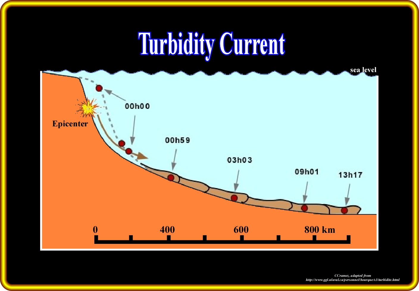
In 1929, the Grand Banks earthquake (Laurentian Slope earthquake) of magnitude 7.2, located about 400 kilometers south of the island (felted as far away as New York and Montreal) and associated to the fault movement of two faults (250 kilometers south of the Burin Peninsula), triggered a large submarine landslide (200 km3). It led to a tsunami that arrived in three waves, each one of 3 - 4 meters high stricking the coast at 105 km/h about three hours after the earthquake occurred. The waves traveled at speeds up to 129 km/h at the epicenter, were recorded as far away as Portugal. The moving down to slope of the turbidite current was restored as illustrated above. During the first hour, on the upper continental slope, the current accelerated and traveled, more or less, 400 km. In the lower part of the continental slope the current decelerated traveling 1000 km (from the epicenter) in around 13 hours. In other words, one can say that turbiditic currents are instantaneous and recurrent-rare geological events (see later).
Sea floor turbiditic currents (characterized by a well-defined front or head, followed by a layer known as the body of the current) are commonly used to describe underwater currents in lakes and oceans, which are usually triggered by earthquakes, slumping, relative sea level falls, sediment-laden rivers, particularly, during flush floods. Since the velocity of a turbiditic current decreases it lose competence (maximum particle size that it is able to transport) and capacity (maximum load a current can transport) and, as a consequence, the deposition of the carried sediments takes place forming the different turbidite deposits.
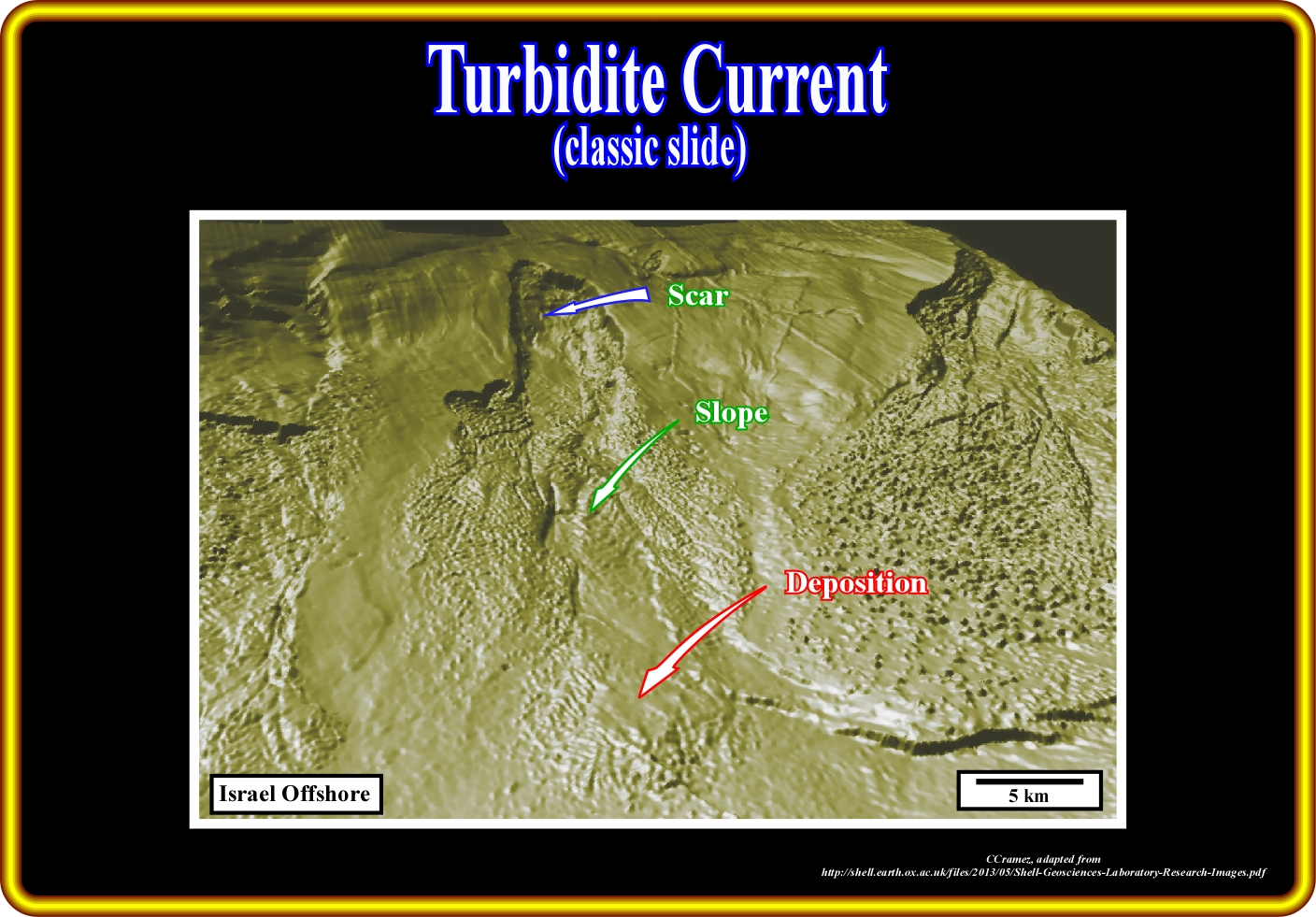
In this sea floor dip attribute image draped over the topography of the Israel offshore, a landslide (turbiditic current) is, easily, recognized at the present bottom of the sea. Here, the turbidite model proposed by P. Vail to explain the lowstand turbidite deposits can not be used, since the turbiditic current, was not initiated by relative sea level fall, but rather by a slope failure, in highstand geological conditions. In this particular case, as in the case of continental rock-slides, the scar, the slope or carpet and the fan (turbidite deposits) are, easily, recognized. The scar is the cirque-shaped depression on the steep slope (valleys and ravines), formed as a result of the surface displacement of masses of loam, abundantly, moistened by ground and surface waters. The slope or carpet corresponds to the higher part of the fan, in which the land mass move down to slope. The fan is the sedimentary lobe, deposited down-dip since the turbiditic current lose competence and capacity.
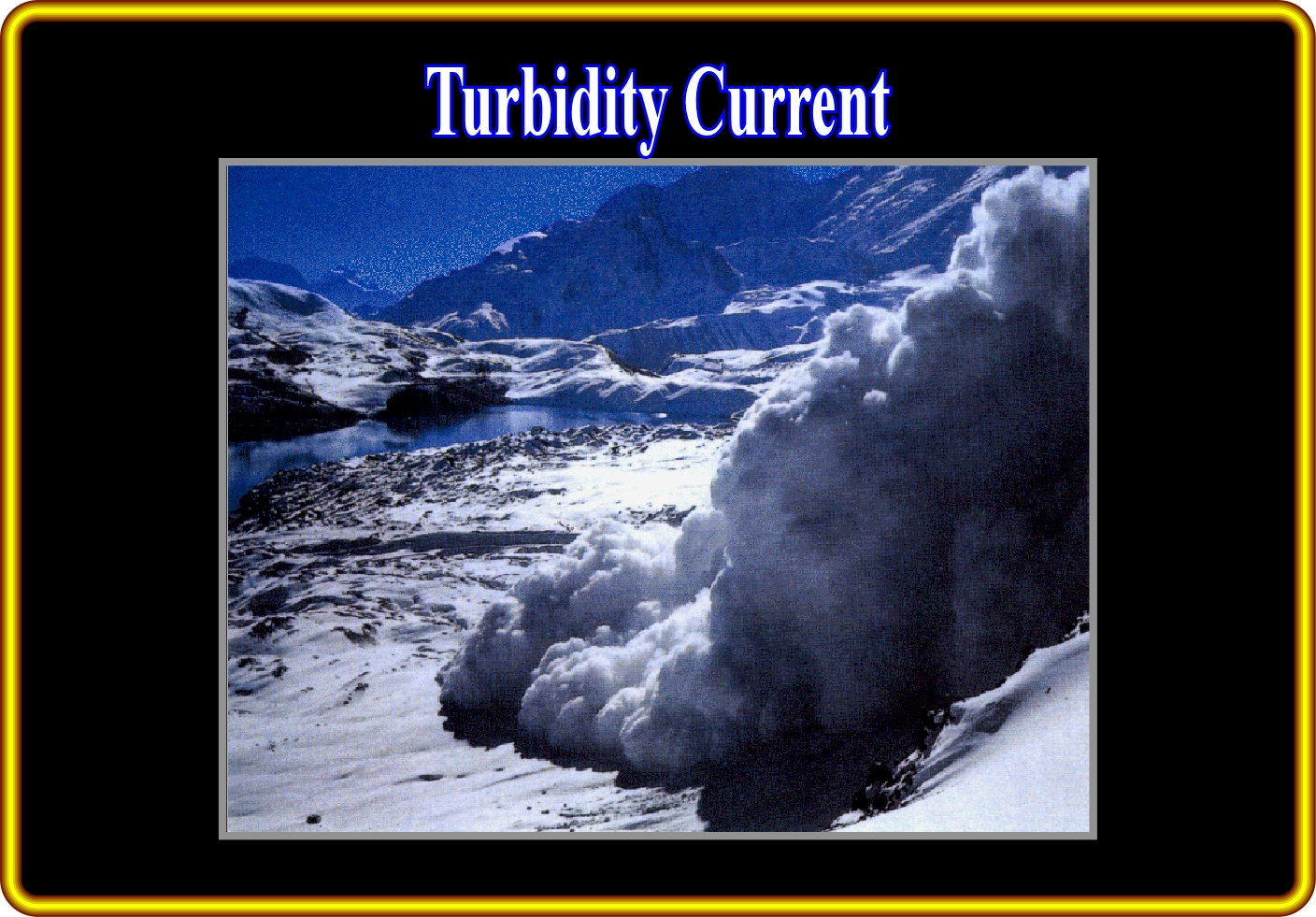
The easiest way to describe a turbidity current is an underwater avalanche. Imagine the cloud of snow and ice that accompanies a snow avalanche as it cascades down a mountainside (left). Turbiditic currents are a bit like that cloud, but they are composed of sediment grains and occur under the sea. When a submarine landslide is triggered, some of the sea floor sediment are picked up by turbiditic currents created by the landslide. Seawater turbiditic currents, like the snow avalanches (known as a turbidity current because of its turbulent nature), races down to slope towards the deep ocean, carrying its sediment load along with it. However, as the current begins to slow down, it no longer has the energy to carry its sediment load and the particles start to settle out onto the sea floor, forming a turbidite deposit.
In petroleum geology, the more interesting turbidite deposits are those associated with sea floor turbidity currents. They can be excellent reservoir rocks and form significant morphological traps. Several geological models have been proposed to explain the fossil turbidite deposits found in the field, sub-surface (petroleum exploration wells) and on seismic line. All turbidite models try to speculate the more likely genesis of turbiditic currents and the characteristics (geometry and facies, i.e., lithology) of the associated deposits. Three major models will be reviewed : (i) Peter Vail's turbidite model ; (ii) E Mutti's turbidite model and (iii) Model invoking upwelling submarine erosion. The Peter Vail's turbidite model explains, quite well, the majority turbidite deposits accumulated during lowstand geological conditions created be significant relative sea level falls, which put the sea level below the shelf break. The Emiliano Mutti's turbidite model explains not only the turbidite deposits amassed during lowstand geological conditions (as Vail's model), but the turbidite deposits accumulated during highstand geological conditions as well. The turbidite deposits piled up during highstand geological conditions (sea level higher than the self break) are, often, associated with flush floods (rapid flooding of geomorphic low-lying areas) caused by heavy rain accompanying severe thunderstorms, hurricanes, tropical storms, or melt-water from ice or snow flowing over ice sheets or snowfields. In the model invoking an upwelling submarine erosion, the turbiditic currents are induced by Eckman's currents (see later). Do not forget that (i) and (iii) try to explain macroscopic turbidite deposits at the scale of the geologic maps and conventional seismic liens, while (ii), try to explain the turbidite deposits as observed at the mesoscopic scale (scale of the outcrops). As might be expected, in the Mutti's turbidite model, bringing forth, at natural scale 1:1, i.e., using field data, there are details than can never be observed in the Vail's model or in the upwelling submarine erosion model, since they are, mainly, based on seismic data.
Contents:
I - Turbidite Deposits in HC Exploration

II- Turbidite Models

III - Geological Events

IV - Completeness and Preservation

V -  Depositional Turbidite Systems

VI -  Turbidite Facies and Related Processes
			A) Bouma's Turbidite Facies
			B) Mutti's Turbidite Facies

VII - Turbidite Systems Classification

			A) Vail's Turbidite Model
					A.1) Sequential Stratigraphy Review
					A.2) Lowstand Systems Tract
							(i) Basin Floor Fan
							(ii) Slope Fan
							(iii) Lowstand Prograding Wedge
                 A.3) Turbidite deposits associated with LST

           B) Mutti's Turbidite Model
				(i) Large Turbidite Systems
				(ii) Medium Turbidite Systems
				(iii) Small Turbidite Systems
							1- Rectilinear Turbidite Channels
							2- Sinuous Turbidite Channels

           C) Submarine Erosion Model
VIII - West Africa Offshore Examples
M) Sierra Leone
Q) Senegal Offshore
IX - Bibliography
to continue press
![]()
Send E-mail to carloscramez@gmail.com or carlos.cramez@bluewin.ch with critics, corrections or commentaries on these Turbidite Depositional Systems notes.
Copyright © 2001CCramez
Last modification : February 2014, May 2022.