
Salt reduction is a mass transfer of salt over time, resulting in an obvious change in area of salt in cross section by :
(1) Volume loss due to dissolution ;
(2) Isochoric flow (unchanged volume) out of the plane of section, including smearing along décollement faults and
(3) Isochoric flow within the plane of section but beyond the ends of the cross section.
Salt Reduction culminates in formation of salt welds or fault welds with development of :
(i) Depocentre and Apparent Mounds ;
(ii) Inversions, Salt Rollers, Relict Rollers and
(iii) Apparent Downlaps.
as illustrate in the following plates.
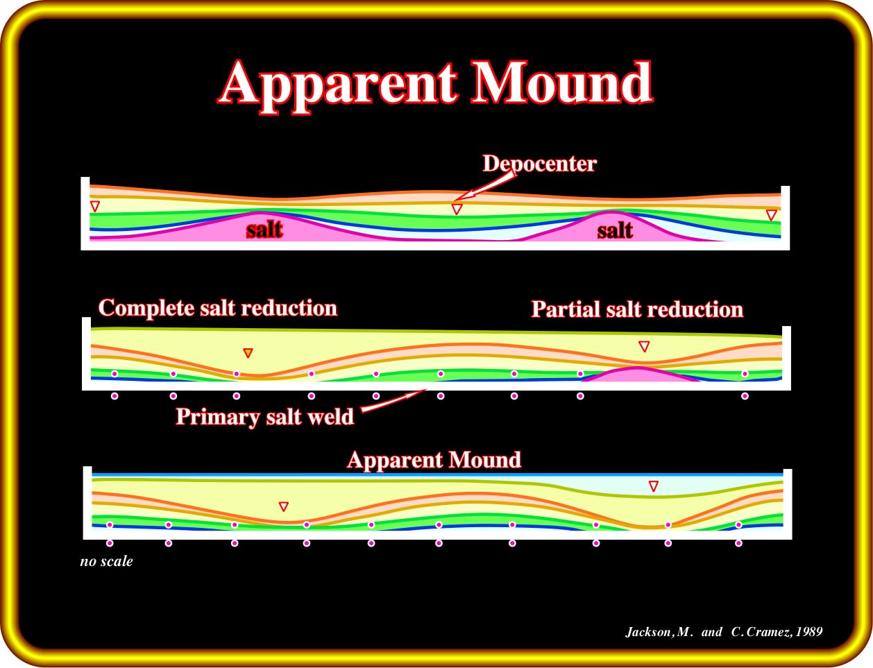
In this sketch, interdomal synforms become apparent mounds by complete salt evacuation, that is to say, by total evacuation of the salt. Depocenters become apparent mounds. They are inverted structures, in which the high structural points become low structural points.
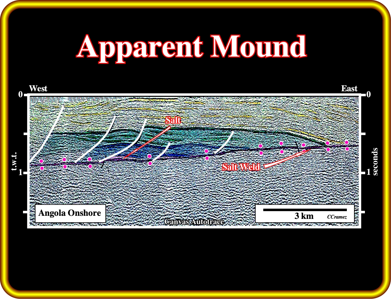
On this old line of the Angola onshore, the antiform structure can be interpreted as an half apparent mound (the western flank is visible in other lines) induced by an almost total evacuation of the allochthonous salt layer. In other words, one can say that the structural high points (the extremities of the structure) became structural low structural points due to salt flowage. Such a salt induced tectonic inversion is completely different of the tectonic inversions created by a reactivation of old normal faults as reverse faults, during an younger compressional tectonic regime, which are, particularly, frequent in divergent margins no Atlantic-type.
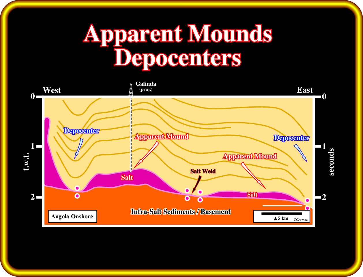
Since longtime, in Angola onshore, apparent mounds and depocenters were recognized as the result of salt reduction. A typical apparent mound is Galinda salt structure drilled by Petrangol in the 50's. On this tentative geological interpretation of an unmigrated old seismic line, two apparent mounds are individualized by salt welds, which are overlain by depocenters. The central salt weld seems to posted the others. On the other hand, the associated the depocentre is not too convincing.
The geological sketch, illustrated below, allow us to understand:
(i) How salt flowage can invert the fault movement of an associated growth-fault ;
(ii) How a salt layer become a down-dip succession of a salt roller and
(iii) How a total salt reduction creates a salt weld and changes salt roller into relic salt rollers.
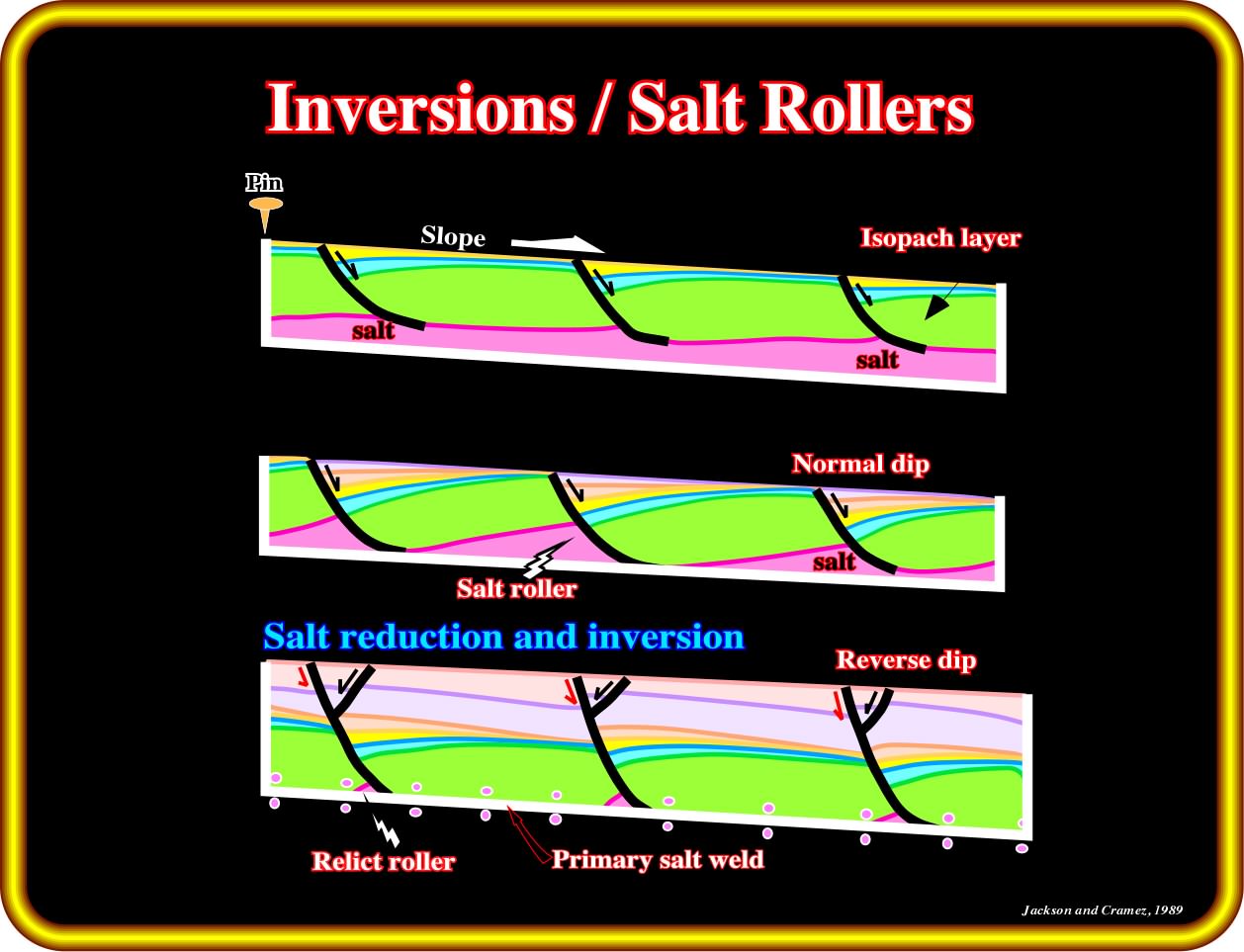
An apparent inversion along the growth-fault planes and relic rollers can be explained by salt tectonics, i.e., by extension and halokinesis. In fact, the geological evolution depicted on this sketch can be summarized as follows: a) Deposition of an isopachous prekinematic interval (in green) above the allochthonous salt layer ; b) Slight seaward tilting of the basin initiates salt flowage (salt flowage creates small basinward growth-fault) ; d) Synkinematic deposition of the blue and yellow intervals ; e) The thickness of the synkinematic intervals increases toward the growth-fault planes, where accumulation (space available or subsidence if eustasy is stillstand) ; f) The continuation of salt flowage creates more space available for sediments in the down-thrown faulted block increasing the normal down-dip movement of the normal faults ; g) At a given degree of salt reduction, the previous continuous salt layer becomes a discontinuous layer composed of a succession of elongated prisms of salt, localized at the down-dip toes of the faulted blocks ; h) Since the landward flanks of the salt rollers shrink, by withdrawal and salt flowage, the overburden collapses ; i) The collapse of the up-thrown sediments creates an inversion of the fault displacement ; the fault plays with a similar movement of those of the reverse faults (the fault movement and geometry of the faulted blocks should not be taken as an evidence of a compressional tectonic regime) ; j) The inverse movement of the fault plane creates space and obliges the sediments of the downthrown block to extend creating normal accommodation faults ; k) When salt reduction becomes almost total, the shrinkage of the salt roller creates relic rollers, which can be laterally disconnected, as illustrated in next plate.
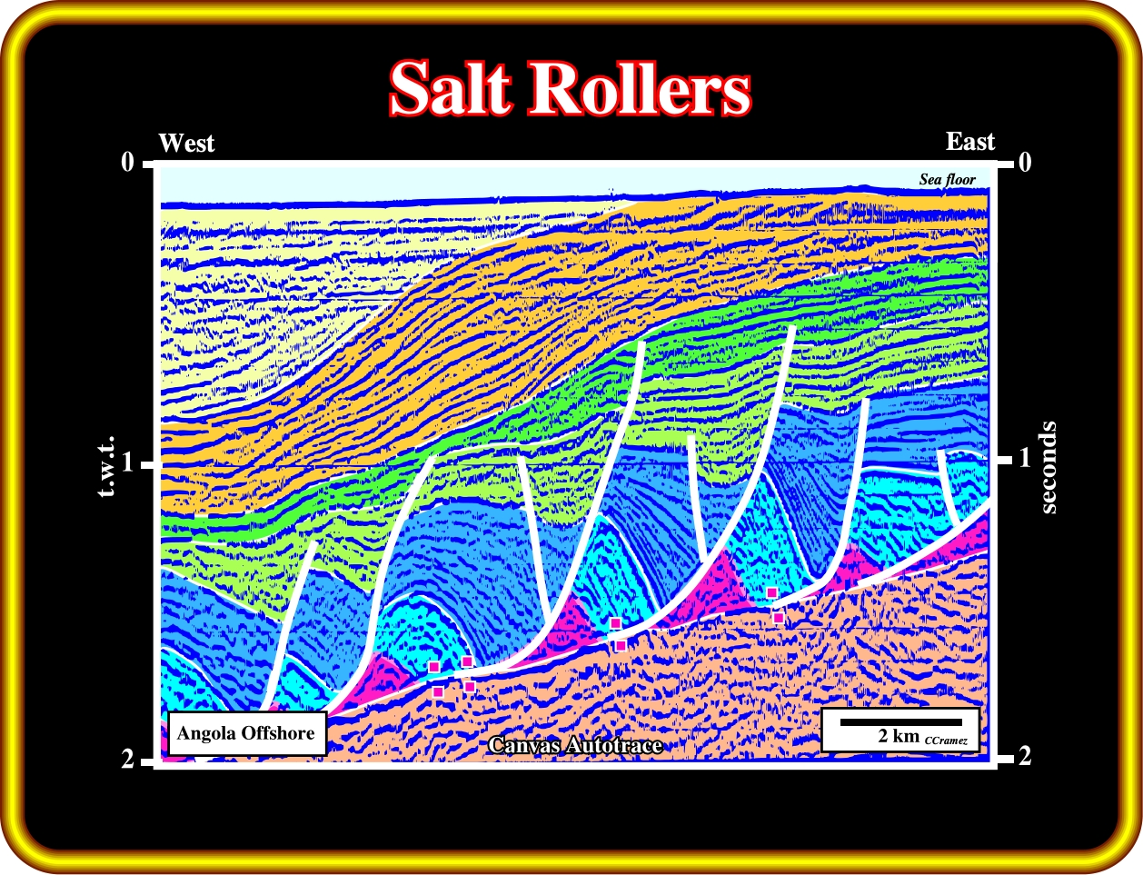
On this geological tentative interpretation line, the shrinkage of the salt rollers is not enough to invert the geometry of the upper stratigraphic intervals of the overburden along the fault planes.
In the next theoretical geological sketch, it is illustrated the normal slip and the reverse dip created by salt reduction, when a salt dome becomes successively a salt roller and then a relic roller.

Taking a look at the unconformity (in red) it is easy to recognize: (i) At the stage of the salt diapir, the movement of the normal-faults is real normal ; (ii) Then, the diapir shrinks and becomes a salt roller ; (iii) The unconformity shows a reverse position, i.e., its position is lower on the up-thrown faulted block than on the downthrown block ; (iv) Finally, if the salt reduction is extreme, the salt roller becomes a relict roller and the inverse displacement is maximum ; (v) The evolution “salt diapir / relict roller” is accompanied by the formation of a fault weld, as illustrated in the next plate.
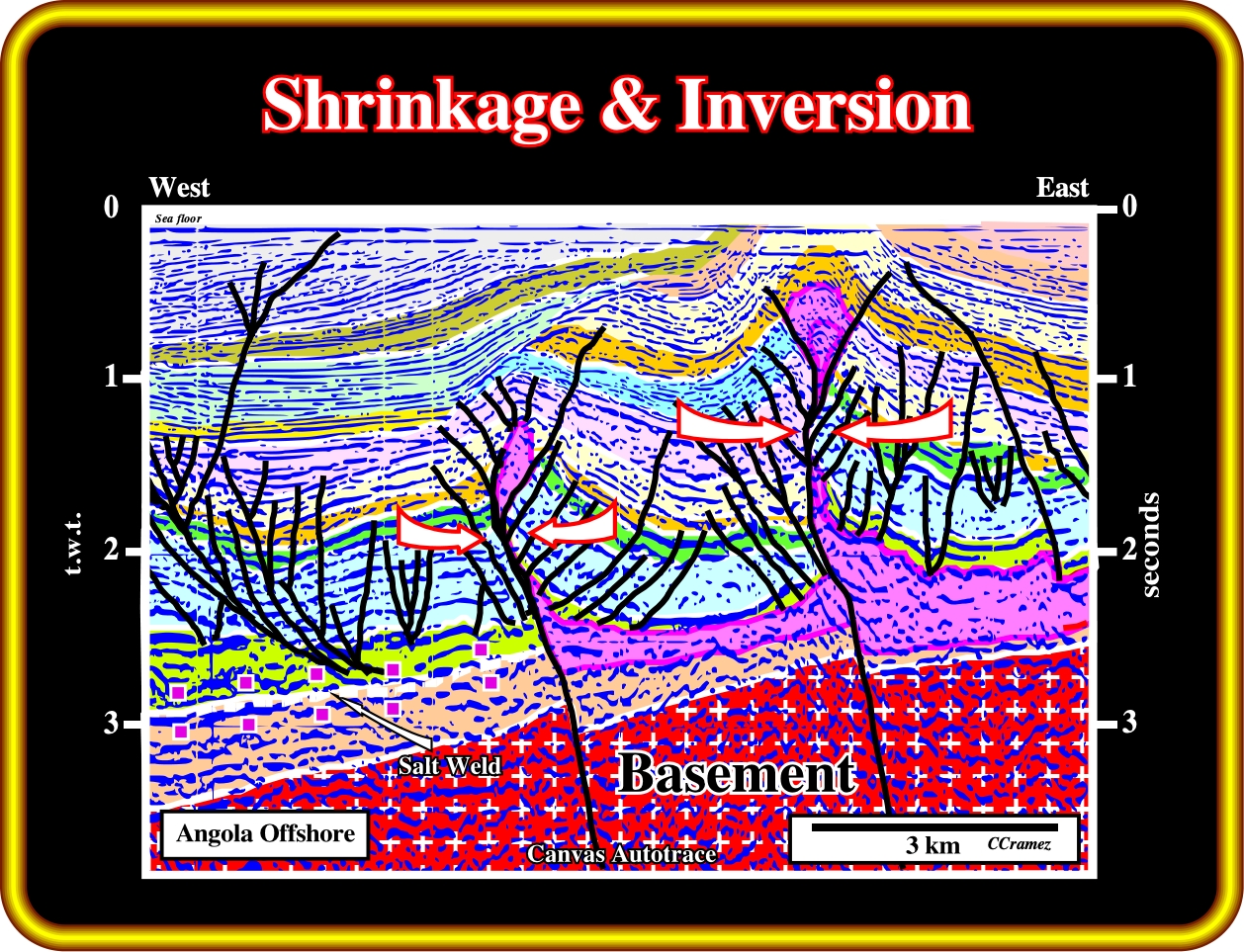
On this geological tentative interpretation, in spite of a late reactivation of the fracture zones (faults affecting the basement), the shrinkage of the western flanks of the diapirs, also, reverses the fault geometry, creating or exaggerating the tectonic inversion.
Salt reduction changes the original reflection terminations and very often induces apparent downlap geometric relationships. The mechanism of such a changes is illustrated below.
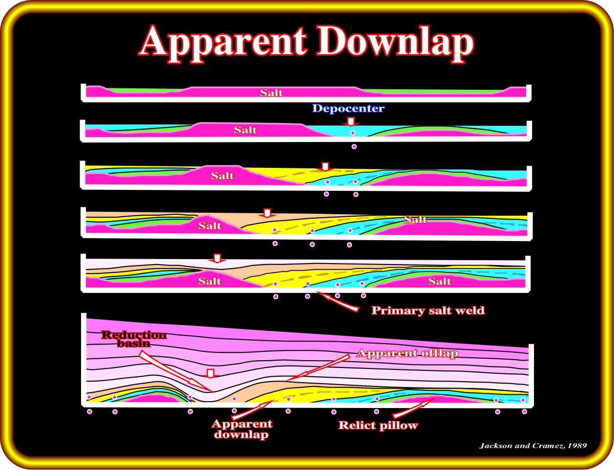
On this evolution, the geometrical relationships are apparent downlaps. In fact, the onlaps are progressively tilted, toward the tectonic disharmony, due to the salt flowage. If the salt evacuation is complete, the tectonic disharmony becomes a primary salt weld (see next plate).
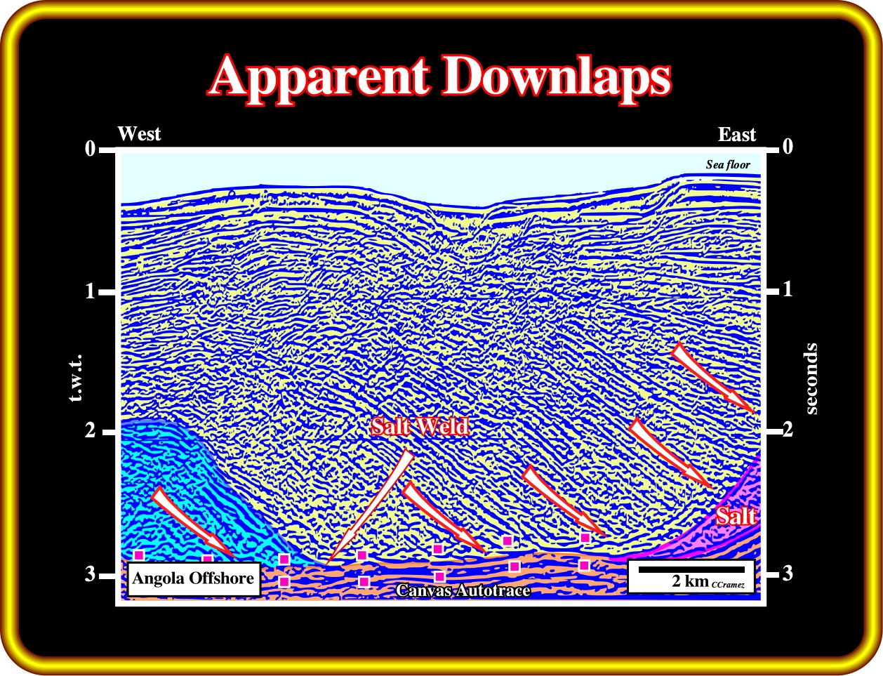
Even without knowing the regional geological setting of the area where this seismic line was shot, the presence of a salt roller, on the right part of the line, strongly suggests that the seismic surface is not a downlap surface, but a tilted onlap surface, induced by salt flow, which creates a wide fault weld.
Exercise 1:
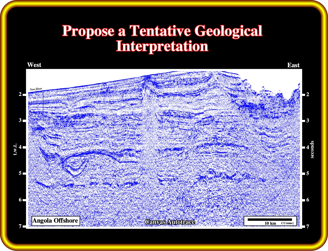
Try to propose a geological tentative interpretation. Pick the bottom of the salt, as well as, the salt welds of different hierarchies. Propose a fault pattern explaining the formation of the salt rollers. Do you see a major seismic artefact on this line? Justify your answer.
Exercise 2:

After you make a geological tentative interpretation, I guess that you see that the N-S anticline structure can be explained by reactivation and inversion of the preexistent normal faulting bordering a rift-type basin. Did you recognize the rift-type basin ? Differentiate the autochthonous and allochthonous salt layers. How do you explain the mini-salt basin in the southwestern part of the line. Can it be explained by salt reduction? Have you individualized a Tertiary salt weld? Where is it located ?
to continue press
next
![]()