
External Forms & Internal Configurations
The overall geometry of a stratigraphic or seismic unit consists of the external form and the internal reflection configuration of the unit. Both must be described to understand the geometric interrelation and depositional setting of the units.
Initial analysis starts, always, in the two-dimensional mode of a single seismic section and these apparent configurations are later corroborated in a three-dimensional grid of seismic sections. Single sections may cut the strata geometry at any angle. However, on these notes, diagrammatic sections illustrating reflections configuration and seismic lines are assumed to be parallel with sedimentary dip unless otherwise indicated.
Strata filling negative geologic features in the underlying sediments define characteristic reflection configurations. Underlying reflections may show either erosional truncation or concordance on the basal surface of the fill unit.
Fill units may be classified by :
a) External Form :
- Channel fill ; - Trough fill ; - Basin fill ; - Front slope fill.
b) Internal Configuration :
- Onlap ; - Mounded onlap ; - Divergent ; - Prograding ; - Complex ; - Chaotic.
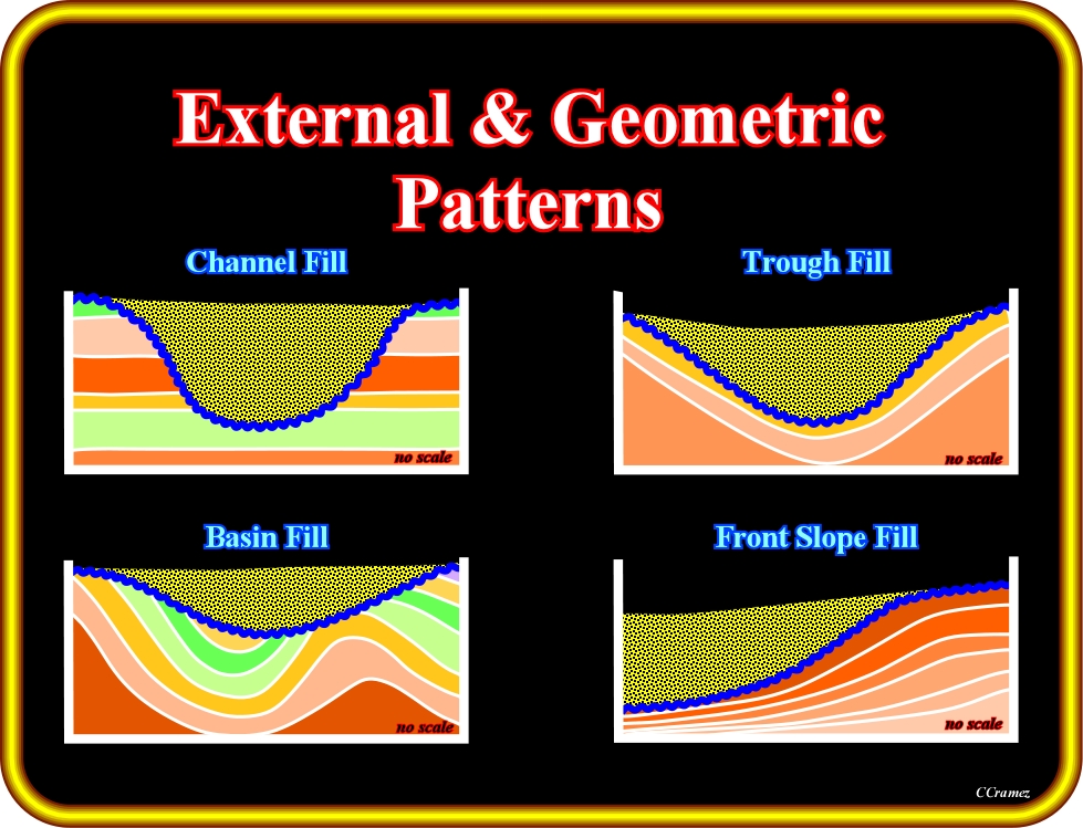
Plate 199- Taking into account the form of infilling units, geoscientists, usually, consider, as picture above, the following major patterns: (i) Channel fill, (ii) Trough fill, (iii) Basin fill and (iv) Front slope fill. The scale of a channel fill and trough fill is, generally, mesoscopic (scale of outcrops characterized by a certain continuity of strata, outcrops), while the scale of a basin fill and a front slope fill is macroscopic (scale of geologic maps, in which the continuity of strata is often not evident).
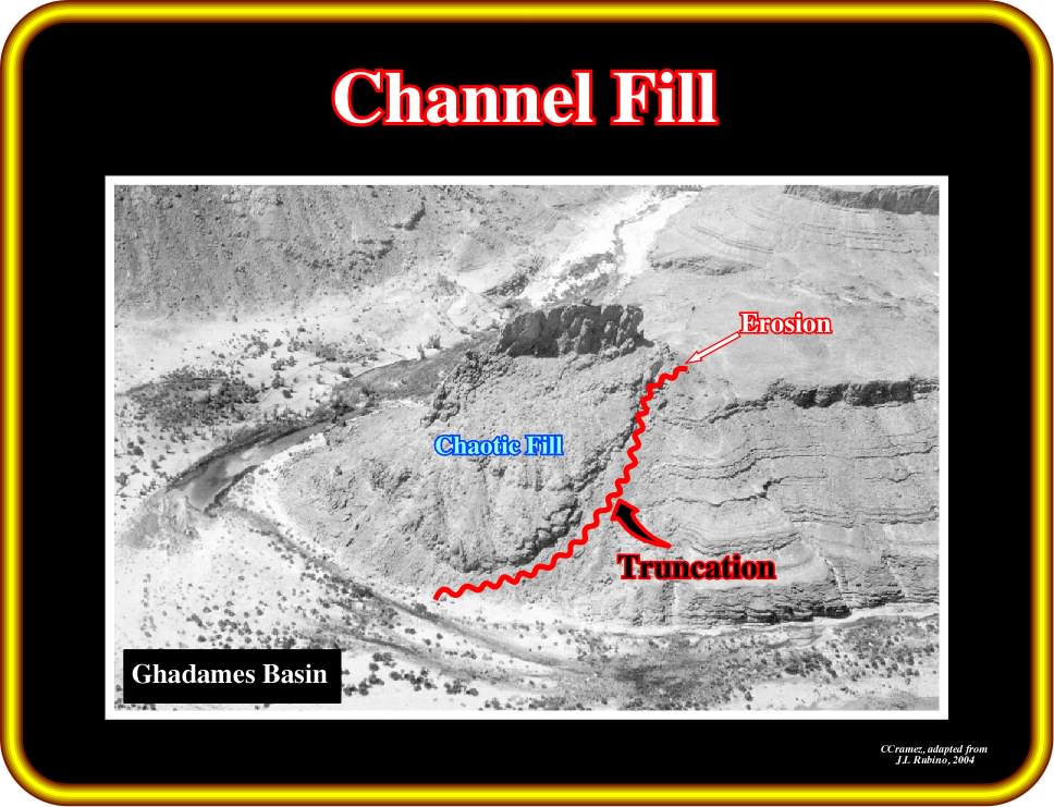
Plate 200 - On this photograph, taking into account the external geometric patterns (truncation), one can recognize a channel fill. The internal infilling configuration can be considered as chaotic. Here, it is relevant to point out that the erosional surface, as well as the filling, are , glacially, controlled. Some geoscientists consider the terms channel fill and channel as synonyms. However, it is obvious that a channel fill and the associated channel are not contemporaneous. A channel fill is not, necessarily, associated with a channel, which ^ is, generally, created by a current or by a stream. Very often, particularly, in deep water, channels and the depressions between turbiditic lobes are filled in retrogradation, when the relative sea level starts to rise.
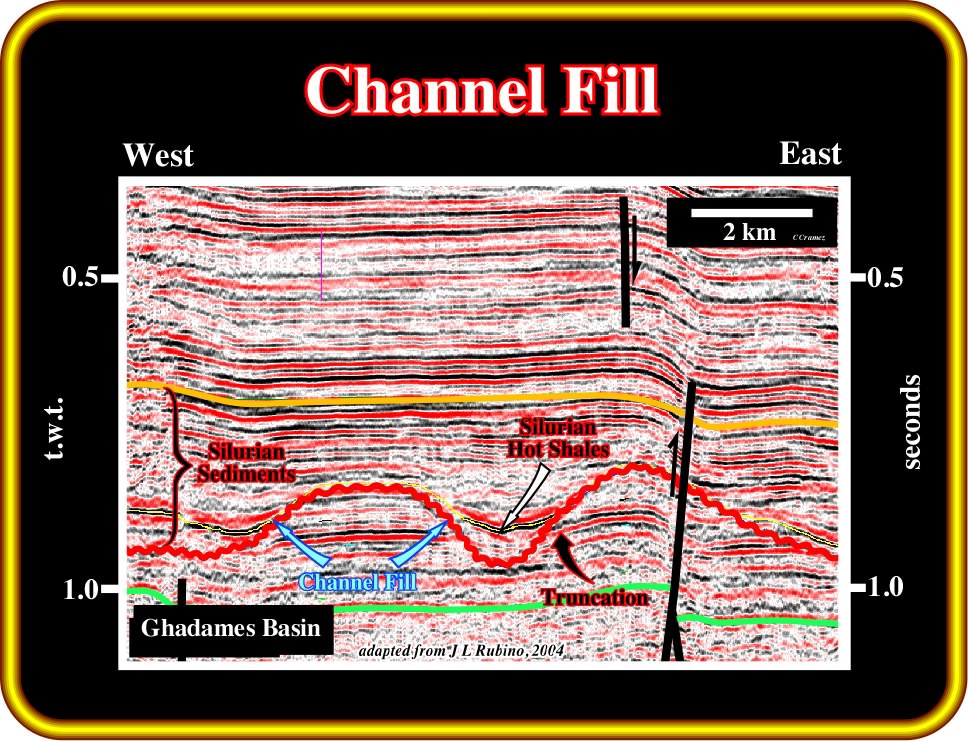
Plate 201 - On this tentative interpretation of an auto-trace of a seismic line of Ghadames basin (Algeria), channel fill patterns are, easily, recognized by the obvious truncation reflection terminations of the Ordovician sediments. The erosion inducing the channel fill geometry is glacially controlled. Later, during the Silurian transgression, these glacial channels were, partially, filled in onlap by Silurian hot shales, which are, by far, the best source-rocks in the basin. The channel infilling process is, totally, independent of the channel creation.
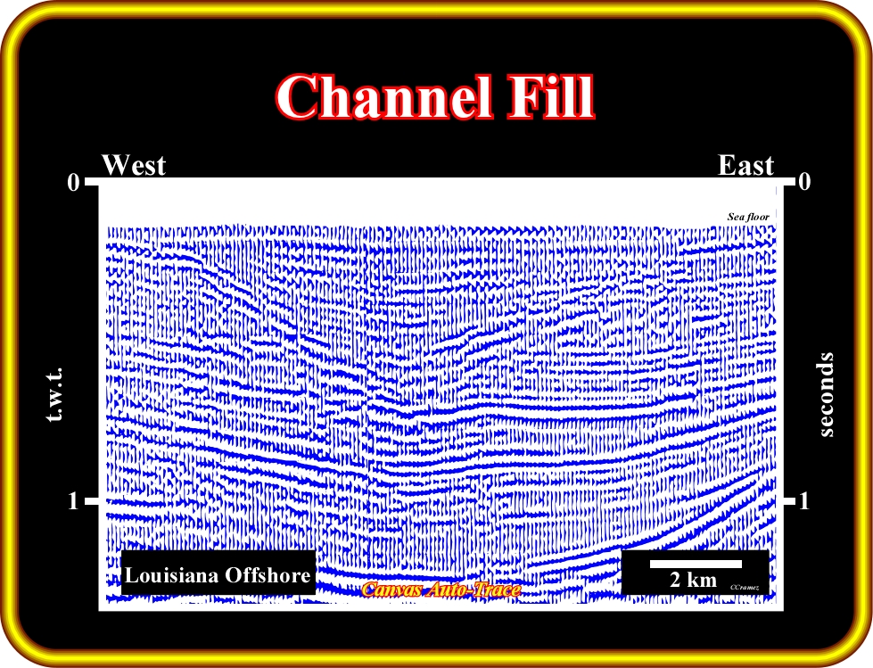
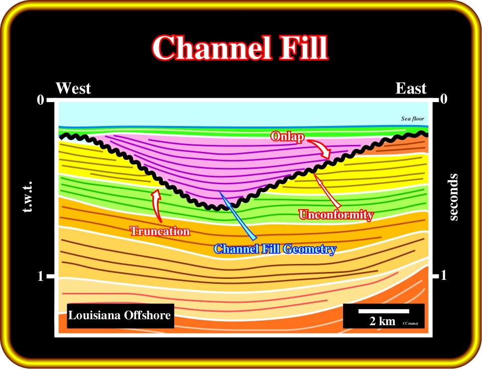
Plate 202 - On this auto-trace tentative interpretation (offshore Louisiana), a relative sea level fall shifted the coastal onlaps basinward and downward (better recognized in perpendicular seismic lines). Sub-aerial erosion took place on the exhumed shelf creating an erosional surface (unconformity) with a typical channel geometry. Later, when relative sea level begin to rise, the negative morphologic features (channels) were filled by the onlapping of a shaly interval (channel fill).
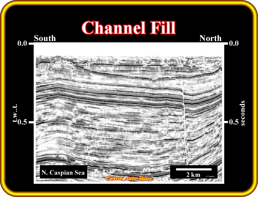
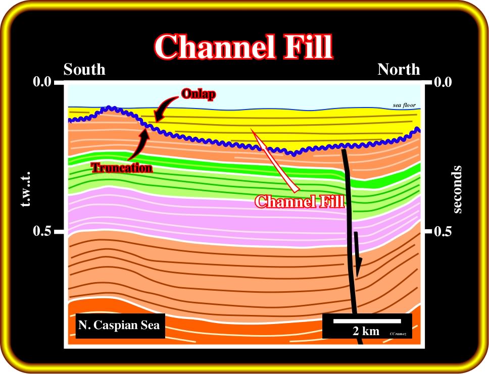
Plate 203 - On this tentative interpretation, a relative sea level fall shifted the coastal onlaps basinward and downward developing a sub-aerial erosion in the exhumed shelf, which created an external channel fill morphology. Later, when relative sea level rose, the shelf was flooded and the channels (long narrow furrows cut by natural processes) were filled, in onlap, by shaly marine sediments. In such geological conditions, the erosional surface is quite regional and the channel fill emphasize an unconformity. A channel fill is an external form older than the infilling, which can have different internal configurations.
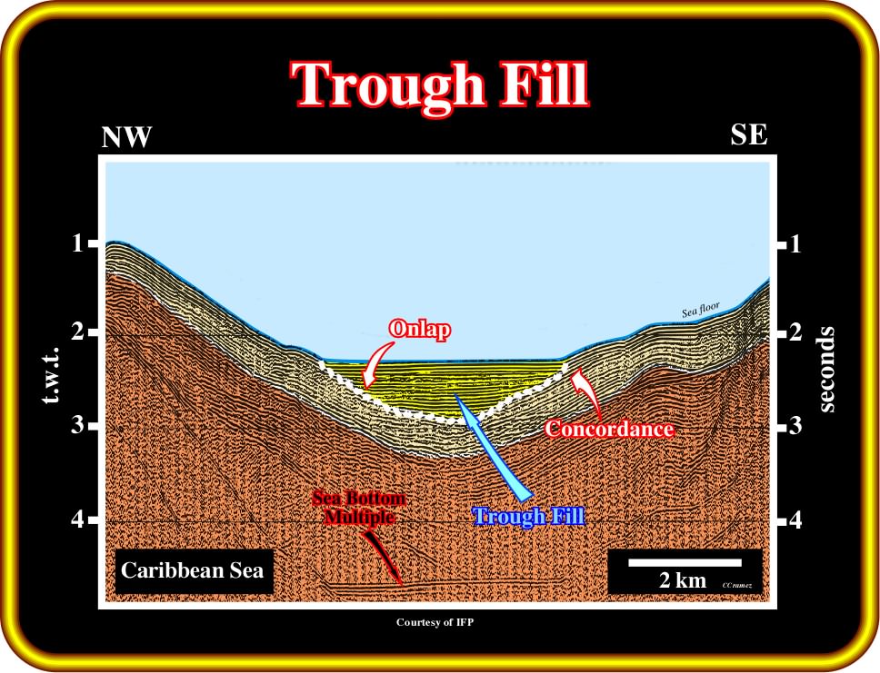
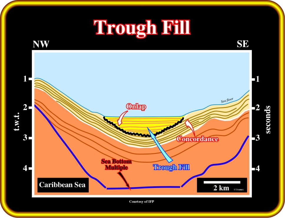
Plate 204 - An external geometry pattern is called trough fill when the depositional anomaly is structural, i.e., when the depositional surface is not created by local or regional erosion. As illustrated on this tentative interpretation (Caribbean Sea), there is no significant erosion between the yellow and underlying the light brown intervals, in spite of the depositional hiatus between them. In such geological conditions, the limit between them does not necessarily correspond to an unconformity. The internal filling configuration of trough fills can vary considerably. At the bottom of this tentative, in blue, a multiple of the sea floor is quite evident.
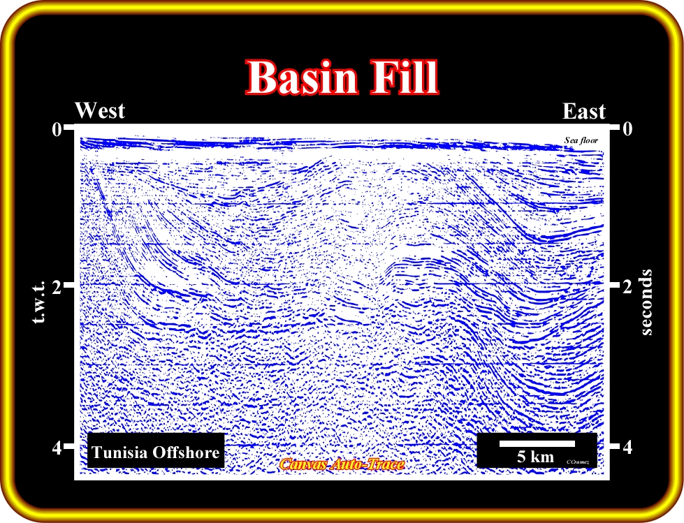
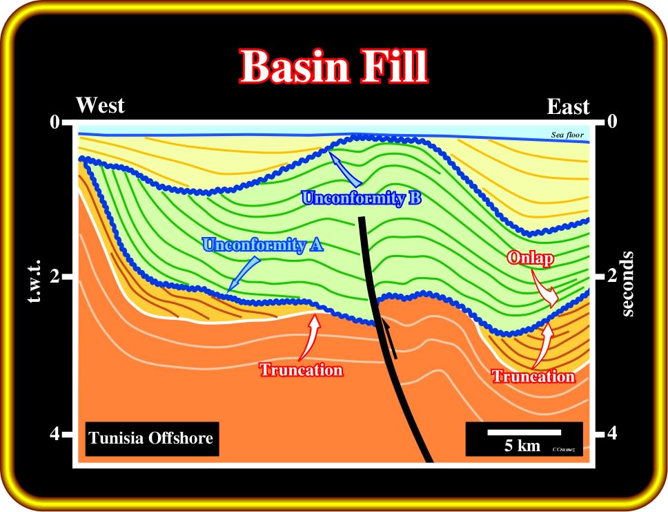
Plate 205 - On this tentative interpretation of an auto-trace of Tunisia offshore seismic line, taking into account the external geometrical pattern, one can say the lower unconformity, at the base of the green interval, corresponds to an external basin fill. Actually, it is quite easy to recognize the underlying reflection terminations highlighting the lower unconformity, which are truncations and the overlying terminations, which correspond to tilted or deformed onlap termination. At least two major compressional tectonic regimes are evident. The oldest pre-dates the lower unconformity, while the youngest post-dates the unconformity B, which, in terms of external fill patterns can be considered as a basin fill. Truncations (below) and onlaps (above) are quite obvious.
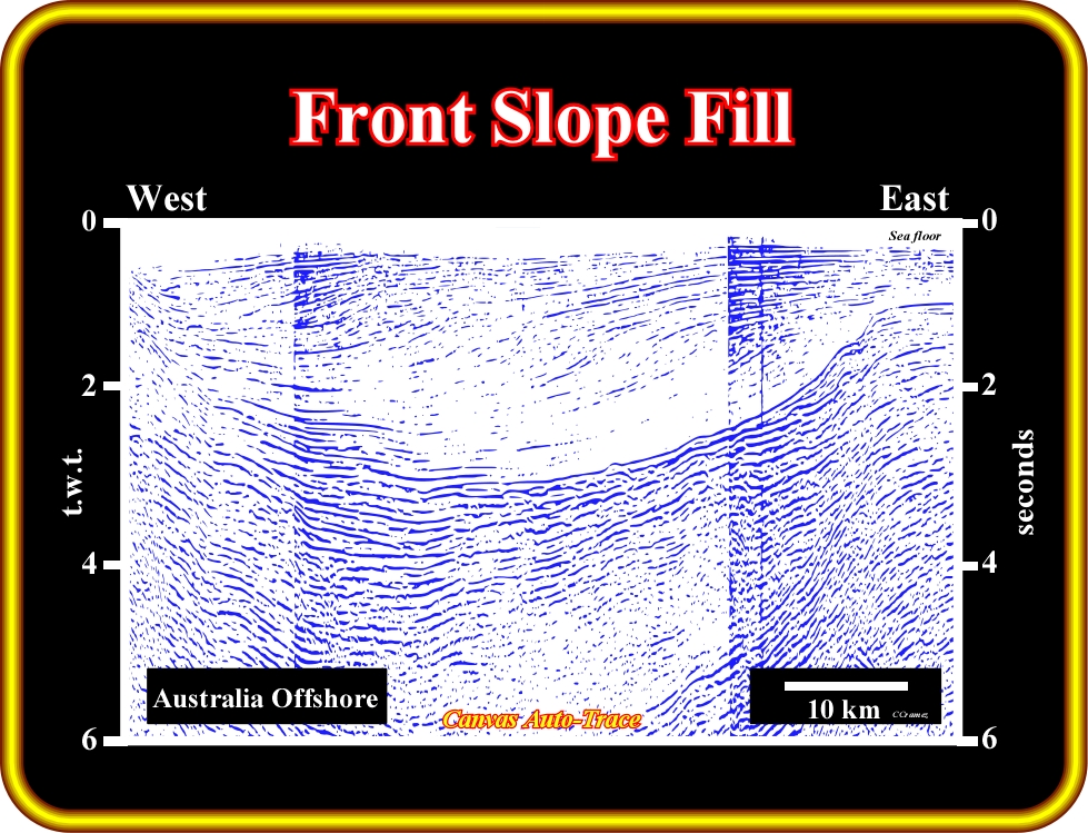
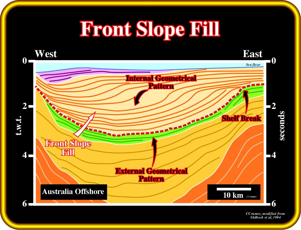
Plate 206 - On this auto-trace tentative interpretation, a front slope fill pattern is illustrated. It is composed by a progradational internal filling configuration. The green seismic interval underlying the front fill depositional surface, corresponds to a front slope fill. There is no significant erosion associated with this front slope fill. The progradation of the successive shelf breaks, limiting the shelf from the continental slope, is recognized, easily, in upper seismic intervals.
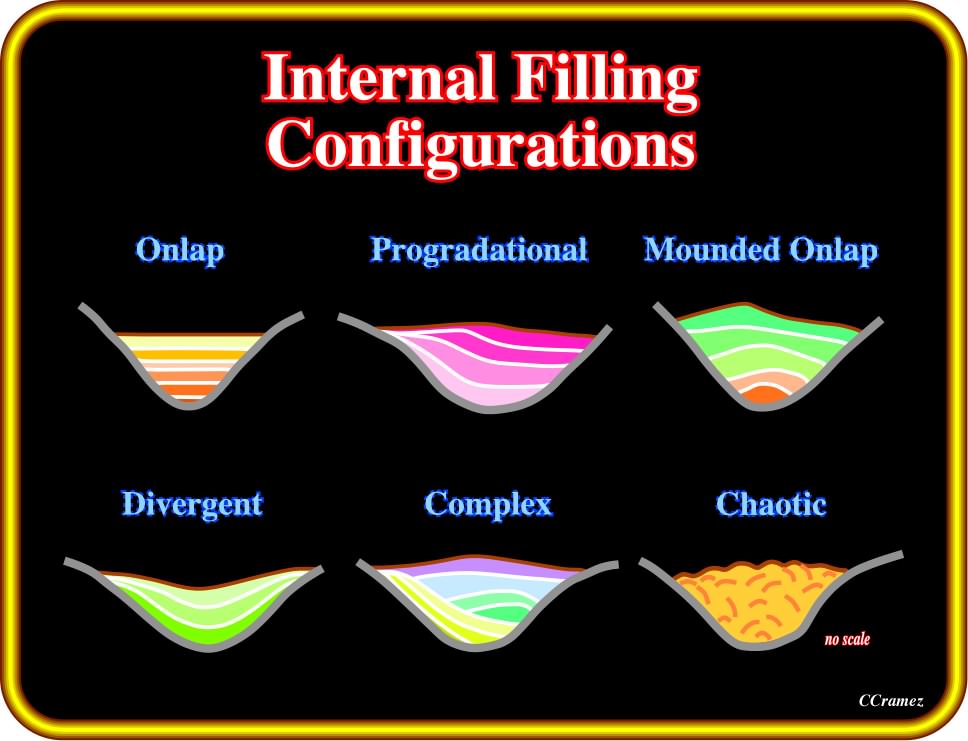
Plate 207 - Taking into account the internal (infilling) geometrical patterns, the fill units can be classified, as depicted above, into: (i) parallel onlap ; (ii) progradation ; (iii) mounding onlap ; (iv) divergent symmetrical onlap ; (v) complex onlap and (vi) chaotic reflectors.
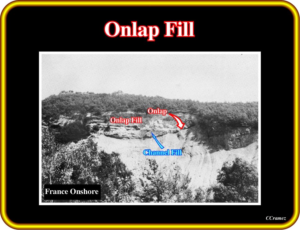
Plate 208- The internal filling configuration is here clearly parallel onlap. The external channel fill geometry seems to be created by the erosion of gravity currents (turbidite currents), since the environment of the scoured sediments is deep water and the regional geological fold belt context, in which deep sediments outcrop due to shortening. The aggradational geometry filling underlines the stacking of slope and basin floor fans (turbidite deposits). In deep-water environments, onlap reflection terminations do not necessary correspond, as it is the case in shallow water deposits, to relative sea level rises (the water depth is big enough to allow deposition even during relative sea level falls). Turbidite depositional systems are, according P. Vail, most, often, deposited during relative sea level falls, that is to say, during lowstand geological conditions. However, according E. Mutti, significant turbidite deposits are also deposited in highstand geological conditions. Internal filling configurations are, also, found in shallow environments, particularly in association with incised valleys. In extensional tectonic regimes, as in Atlantic-type divergent margins, all outcropping external channel fill geometries, correspond to incised valleys (e.g., onshore Kwanza geographic basin, Angola).
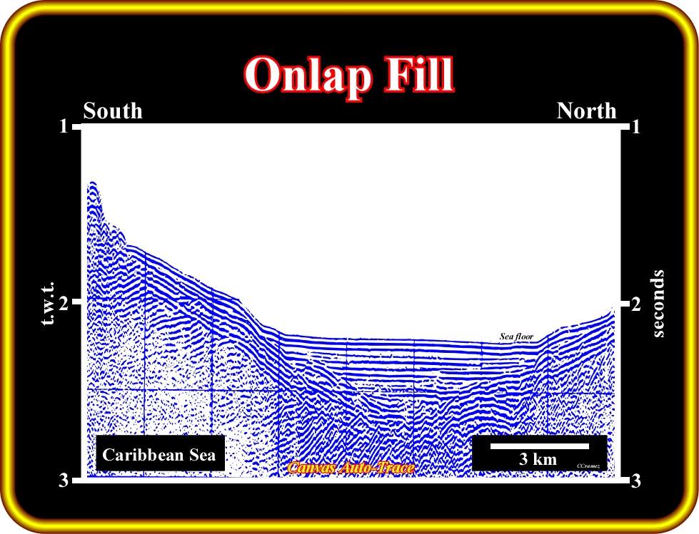
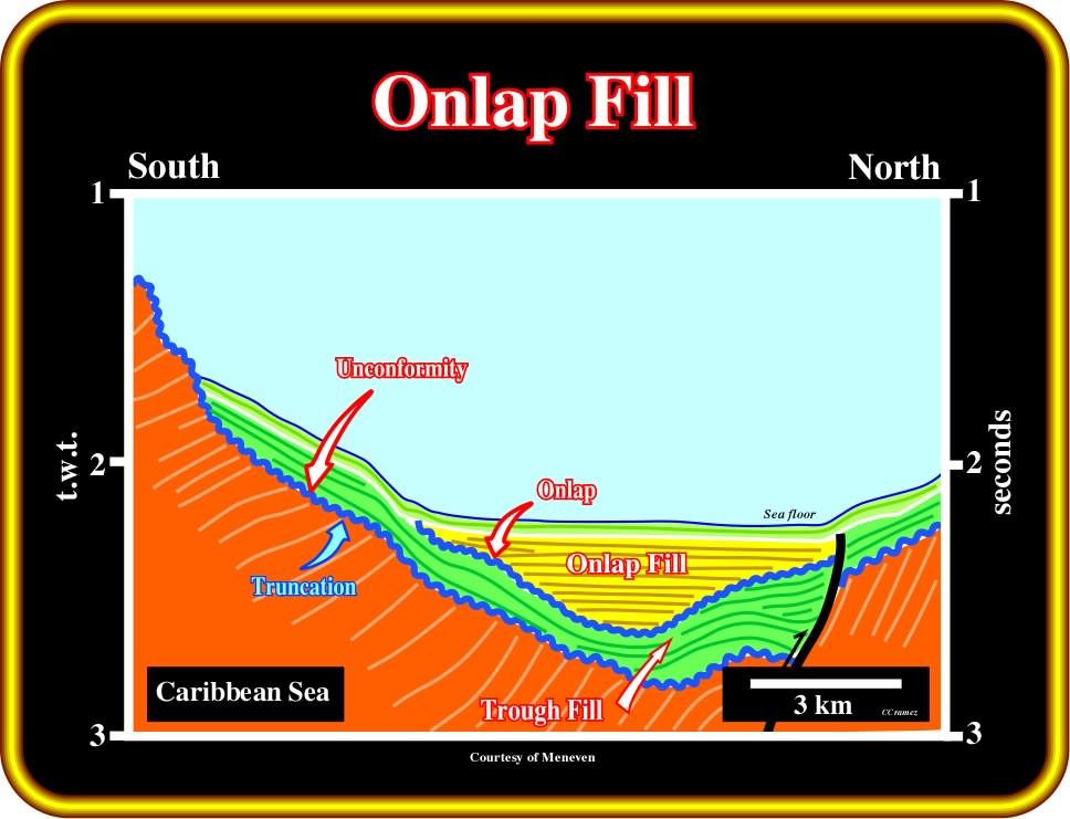
Plate 209- This tentative interpretation shows the difference between an unconformity (erosional surface or the basinward correlatable conformity) and a trough fill. Unconformities, as depicted above, are, here, characterized by underlying truncation reflection terminations. In a trough fill there is no underlying reflection terminations. There is concordance. On this tentative interpretation, the structurally induced trough fill was fossilized by deep-water sediments with an internal onlap fill geometry (at least in the N-S direction).
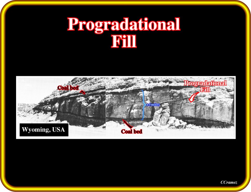
Plate 210 - A progradational reflection configuration, as illustrated on this photograph, can be interpreted as strata that were deposited due to lateral outbuilding or progradation. Sigmoid, oblique, complex, shingled and hummocky progradational patterns are developed by progressive lateral development of gently sloping depositional surfaces, called clinoforms (sub-aqueous landforms, such as the continental slope of the ocean or the foreset bed of a delta, http://encyclopedia2.thefreedictionary.com/clinoform). Differences in prograding clinoforms result in large part from variations in the rate of deposition and water depth.
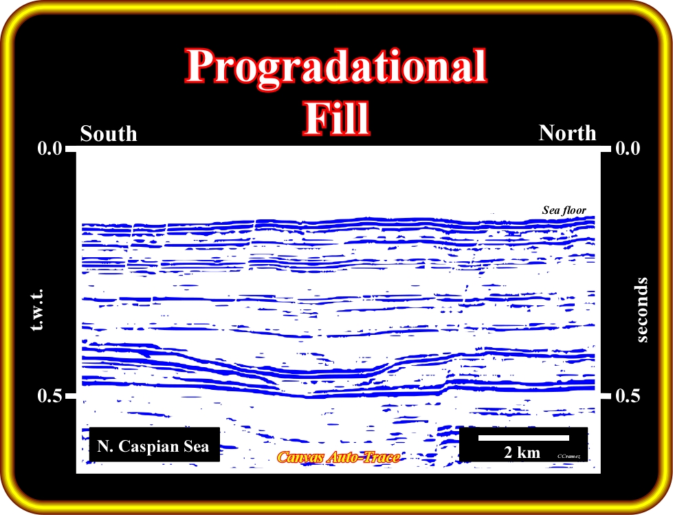
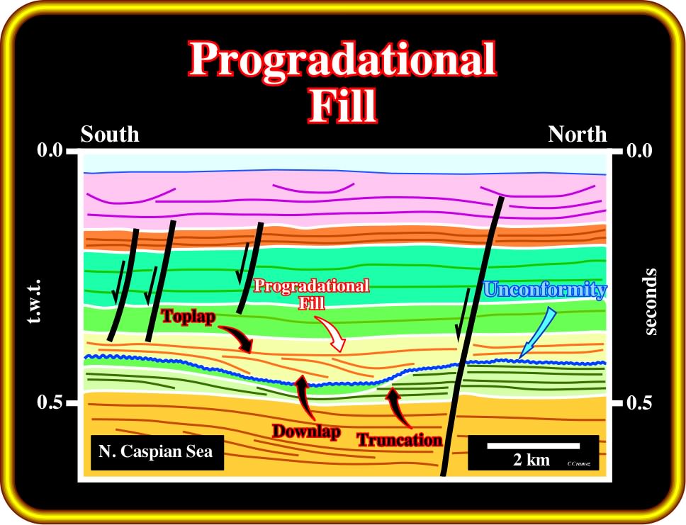
Plate 211 - On this auto-trace tentative interpretation, an incised valley (see horizontal scale), created during a relative sea level fall, was later infilled by progradational sediments as indicated by the downlap reflection terminations. The downlaps, strongly, suggest a terrigeneous influx coming from south. Quite often, incised valleys, particularly, those located near the shelf break, are filled by late lowstand and transgressive sediments, which at a small scale can show a forestepping geometry. The source of clastics sediments is the continent. In shallow water environments, incised valleys are, by far, the best indicators of unconformities (not enhanced by tectonics), that is to say, of relative sea level falls.
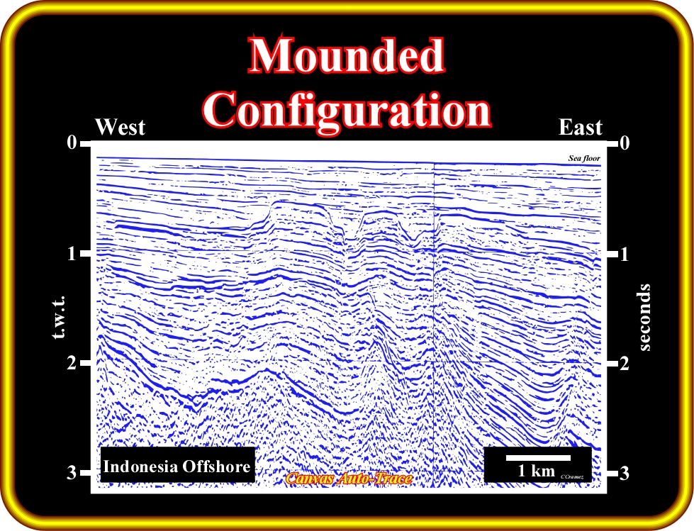
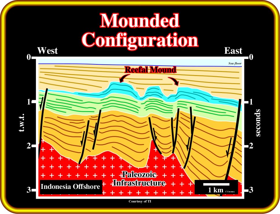
Plate 212 - Mounded reflection configurations are interpreted as strata forming elevations or prominences (bulges) rising above the general level of the surrounding strata. Most mounds (natural elevation of earth, hillock or knoll) are topographic buildups resulting from either clastic, volcanic depositional processes, or organic growth. In lower part of certain Atlantic-type divergent margins (Angola, Brazil), travertine mounds form quite good petroleum morphological traps and reservoirs-rocks. They are deposited through the rapid precipitation of calcium carbonate, especially, at the mouth of a hot spring associated to faults. On this tentative interpretation of an auto-trace of a seismic line from Indonesia offshore, the mounded configurations (light blue) are, likely, associated with reefal buildups.
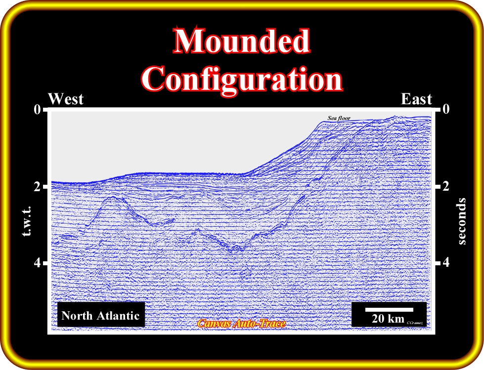
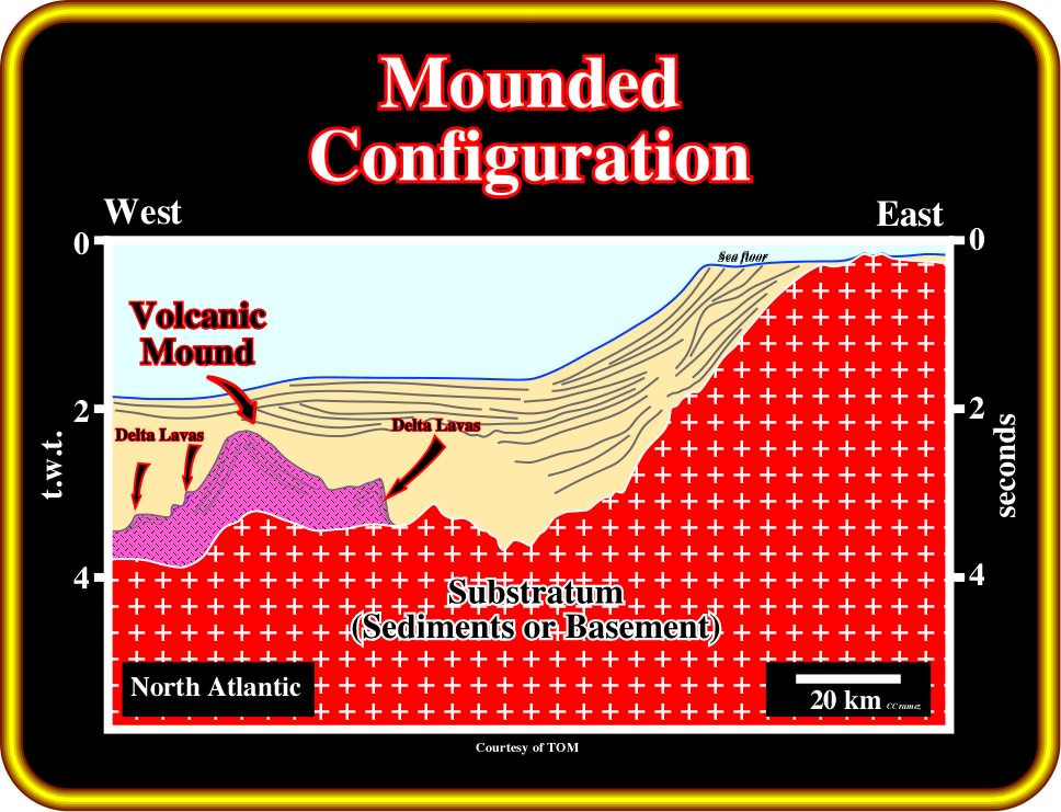
Plate 213- Volcanic mounds are quite frequent, particularly, in the North Atlantic from where the seismic line of this geological tentative interpretation comes. In this particular example (Darwin seamount), the volcanic mound corresponds to a seamount, with which lava deltas and sub-aerial lava-flows (seaward dipping reflections) are, often, associated. It is important to point out that volcanic material cannot flow under water : it is, quickly, frozen. The development of lava deltas is due to such behavior.
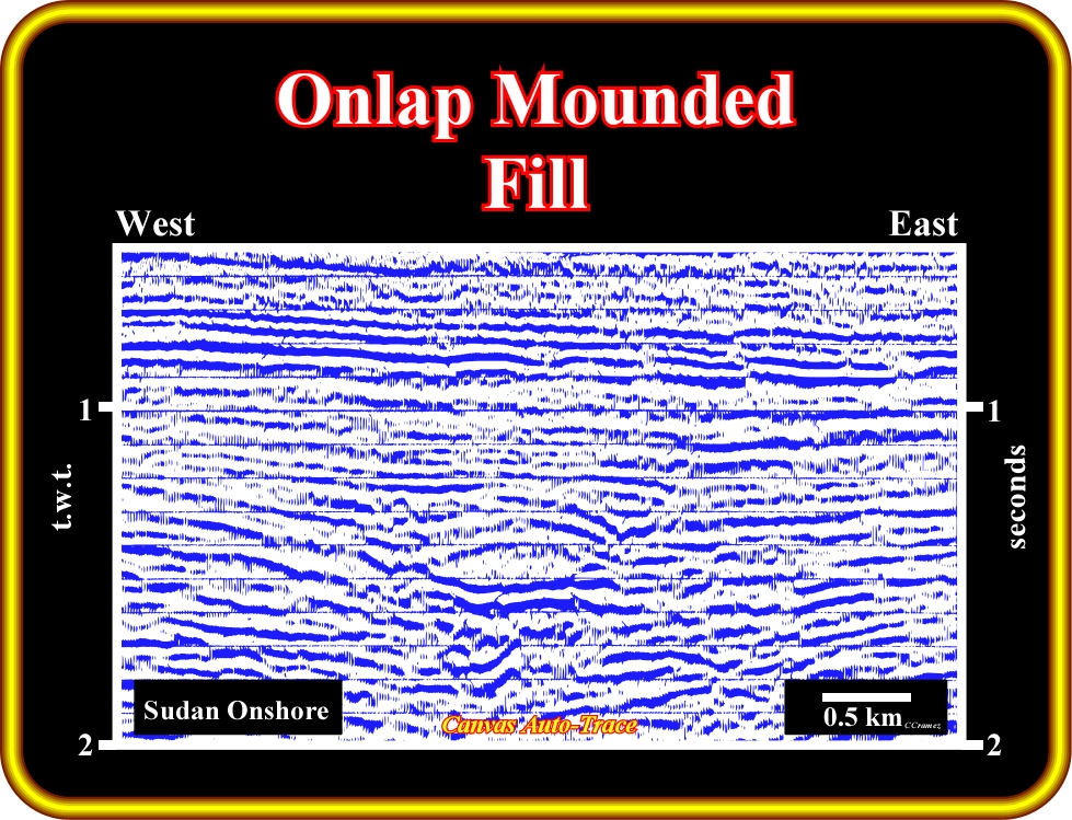
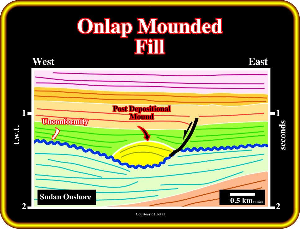
Plate 214- Mounded geometries and, particularly, onlap mounded reflection configurations can be post-depositional. Actually, as depicted on this tentative interpretation of an auto-trace of a seismic seismic line from Sudan onshore (Piber Post Basin), the onlap mound configuration was created due to differential compaction of the sediments. The sandy facies filling the channel morphology are less compactable than its surrounding shale sediments. Often, geoscientists used differential compaction to predict if a channel is filled by sandstones (onlap mound) or clays (absence of onlap mound).
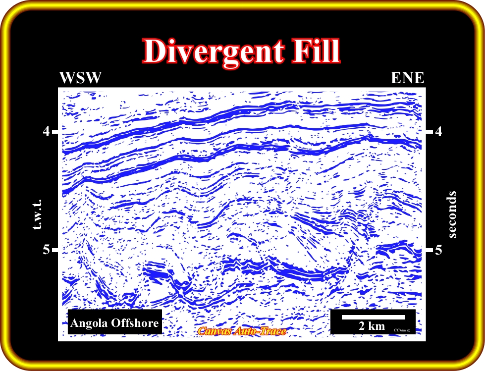
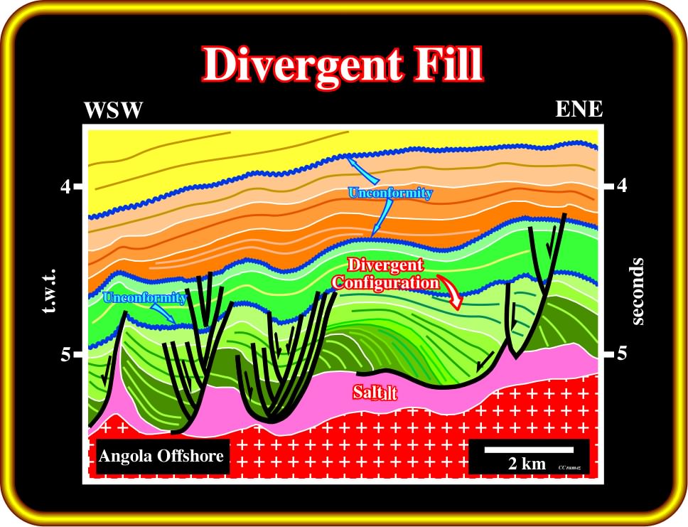
Plate 215 - Divergent fill or divergent reflection configuration is characterized by a wedge-shaped unit in which most of the lateral thickening is accomplished by thickening of individual reflection cycles within the unit, rather than by onlap, toplap or erosion at the base or at the top of the stratigraphic cycle. Divergent configurations suggest lateral variations in the rate of deposition, or progressive tilting of the depositional surface as illustrated on this tentative interpretation of an auto-trace of an Angola offshore seismic line. The area with less subsidence, that is to say, the hinge area is favorable to the development of potential carbonate reservoirs, while the area more subsidence (near the fault plane) is conducive to deposition of potential sandstone reservoir-rocks. If the facies is carbonate, the more likely reservoirs are in areas with less subsidence (small thickness or less divergent), if the facies is sandy, the more likely reservoirs are in the area of maximal subsidence (higher thickness or more divergent). As salt induced tectonic inversions are possible, the area with less subsidence is not, necessarily, always a structural high.
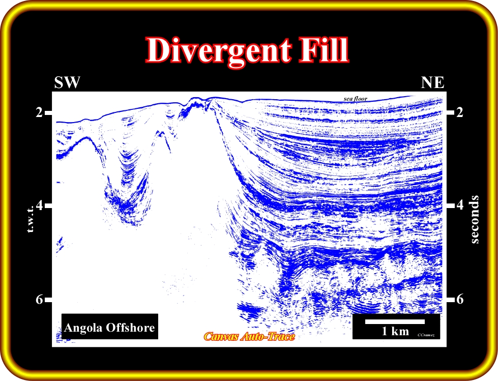
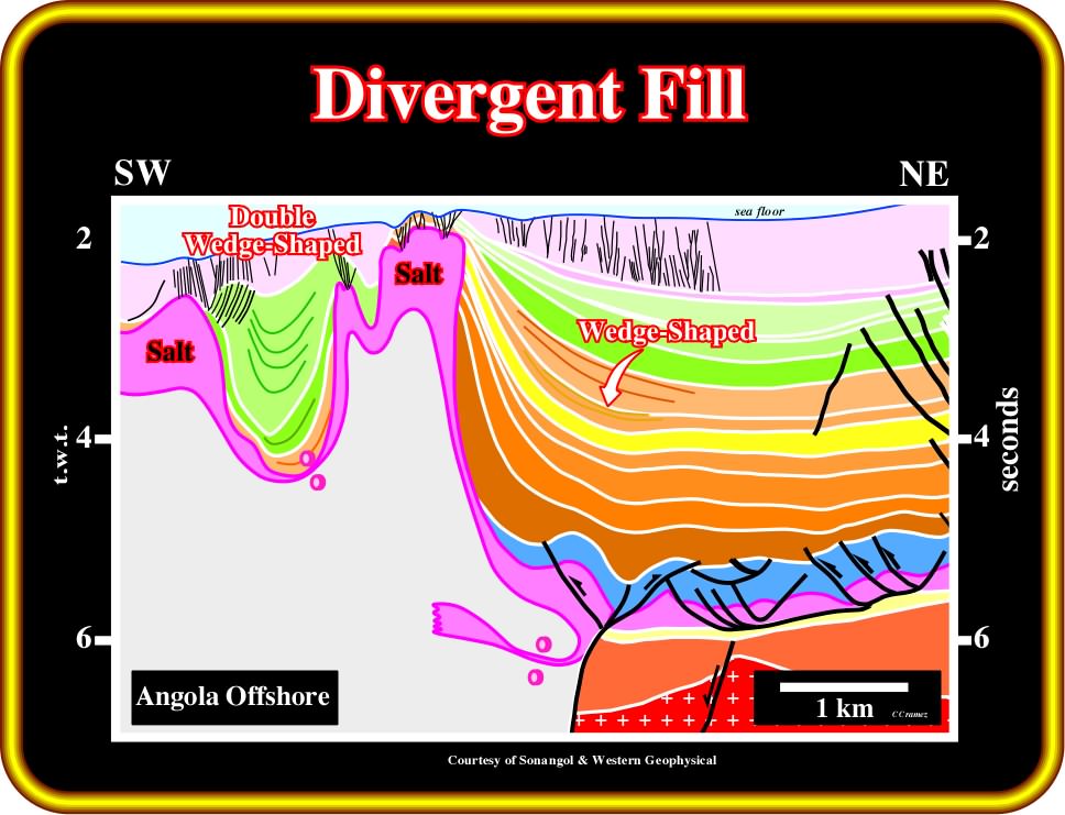
Plate 216 - On this tentative interpretation of an auto-trace of a seismic line of Angola deep-water, divergent wedge-shaped configurations are, mainly, associated with compensatory subsidence induced by salt flowage. In association with allochthonous salt layers (found in a place other than where they and their constituents were formed), salt expulsion basins (mini-basins) are, almost always, filled by double wedge-shaped convergent sediments. Such a convergent configuration suggests an increasing of compensatory subsidence toward the center of the basin.
to continue press
