
c) Middle Member: Slope Fan (SF)
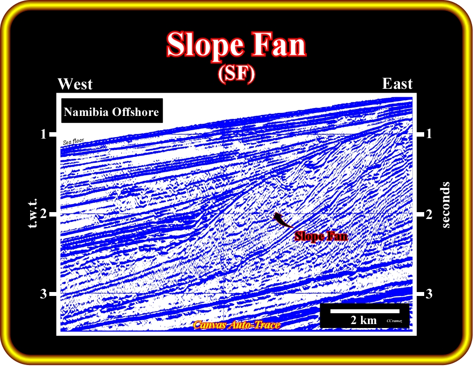
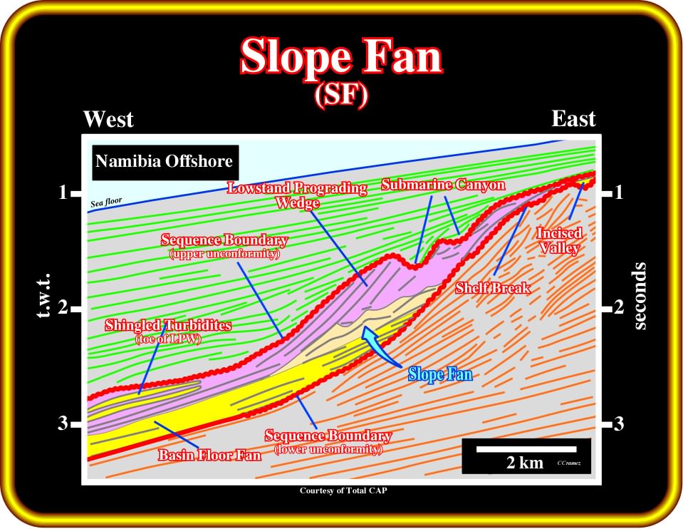
Plate 387 - Taking again this detail of this tentative interpretation of an auto-trace of a seismic line of Namibia offshore, the middle member of a lowstand systems tract, i.e., a slope fan (SF), in light brown, can be illustrated. It overlies a basin floor fan (BFF), in yellow, and is overlain by a lowstand prograding wedge (LPW), in violet. On the next pages, the main characteristics of the slope fan are reviewed.
1) Slope fan time is a period of major headward erosion and bank collapse of the submarine canyons. Basin subsidence begins to create a very slow rise in the position of the sea level relative to the basin margin, as the rate of eustatic sea level fall slows and approaches zero at the lowest part of the eustatic cycle.
2) Seismic expression of the slope fan varies widely :
a) Externally, a submanrine fan appears as a broad thick apron of sediments with the thickest and crestal position opposite the source supply/ a submarine canyon.
b) Internally, recognizable seismic facies patterns include slumped deposits from delta and from adjacent flanks, the typical “gull wing” pattern of submarine channels and a discontinuous pattern associated with over-bank sands near the crest of the slope fan.
3) Submarine channel sands make excellent exploration targets, particularly if they are identifiable seismically due to gas saturation.
4) Over-bank sands are thin, often below the resolution of the conventional logging tools, but their porosity and permeability may be startling high.
5) Over-bank sands are apparently created when the supply to a submarine channel exceeds the transport capacity of that conduit and sands well up over the levee and are, widely, spread in a thin sheet over the slope fan apron.
6) Over-bank sands appear to trap against the levee facies or channel fill shales (clay-plug). In thick accumulations over bank sands may form a very large stratigraphic trap composed of many thin sands. A high level of petrophysical and well testing technology is needed to recognize and properly evaluate such a trap.
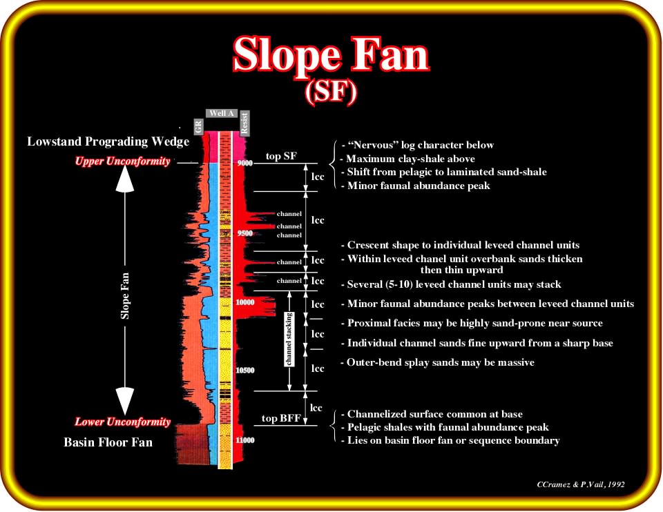
Plate 388- The main characteristics of the log patterns of slope fans are summarized in this plate. A channel fill and particularly a stacking of channel fills are underlined in a gamma ray or SP log by a blocky shape with a particularly sharp upper boundary. Channel levee complexes induce a typical nervous log response. Stacking of channel fills, when overlying a basin floor fan, are often difficult to recognize on electrical logs particularly when the apron shales, which generally are at the base of a slope fan, are absent.
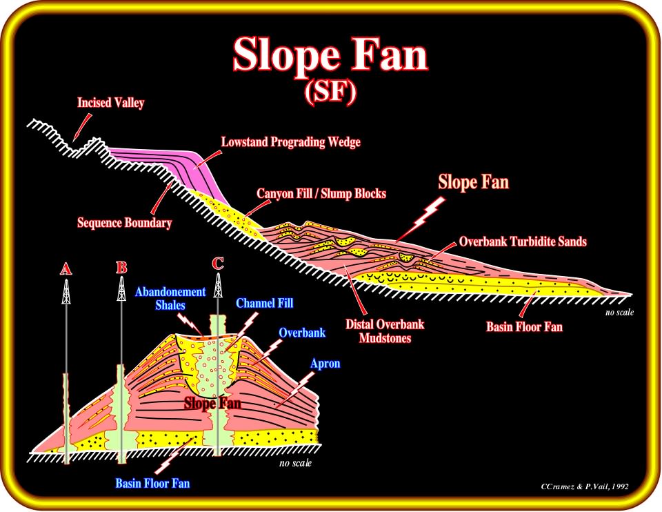
Plate 389- This geological model, proposed by P. Vail, summarizes the chief characteristics of a lowstand systems tract (LST) and particularly those of a slope fan, in which the channel levee complexes are paramount. In a slope fan, reservoir predictions require a good understanding of the depositional model of the channel levees. On this plate, the main reservoir-rocks are localized in the channel fills. The reservoirs in the over-bank deposits, as suggested, previously, and as depicted above, are quite thin and confined. When slope fans are the main reservoir interval, explorationists must employ very good seismic data, if possible 3D, in order to predict the more likely location of the channel fills, where the thickness and lateral coalescence of the reservoir-rocks is large enough to trap economic amounts of hydrocarbons.
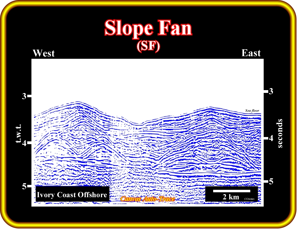
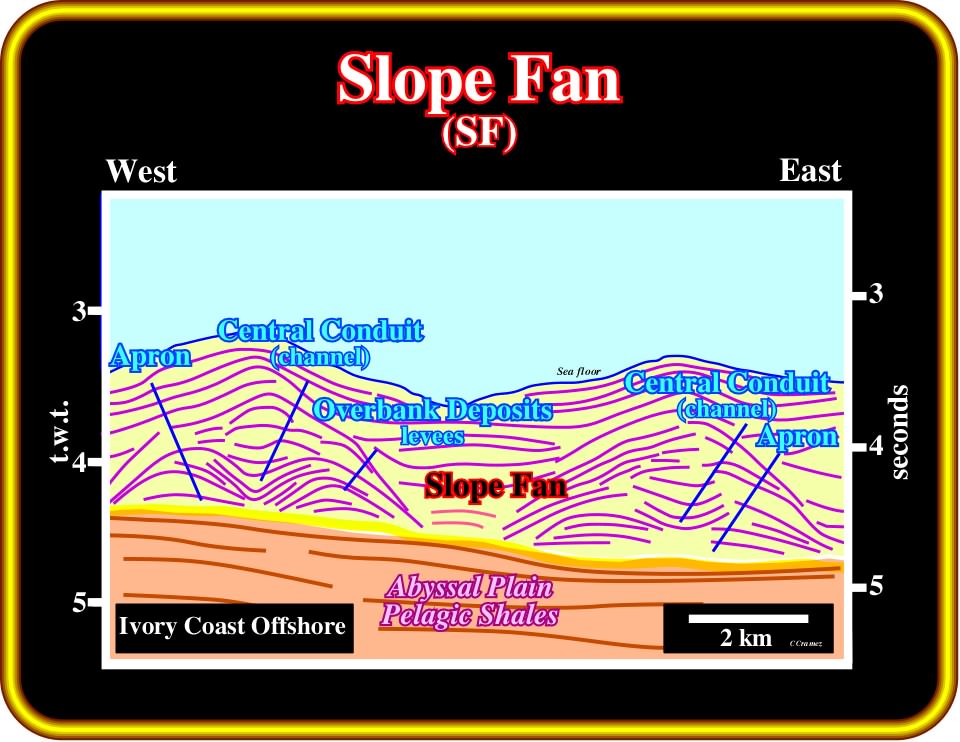
Plate 390- This auto-trace of a seismic line from deep water Ivory Coast illustrates the strike geometry of a channel levee depositional system. Contrariwise to fluvial channel-leveed complexes, the basal geometry is flat. Turbidite currents do not need a bed, as a river. As deposition takes place, the central area, where the current has a higher competence, stays starved (without deposited sediments). The next turbidite current uses it to pass through. Gradually, the turbidite currents become channelized, and every time their thickness is higher than the walls of the central depression (often labeled turbidite channel), the currents over-bank and lay down sediments to form what we, usually call turbidite levees. When turbidite supply exceeds the transport capacity of the central conduit, sediments well up over the banks and are spread widely in thin sheets over the slope fan apron.
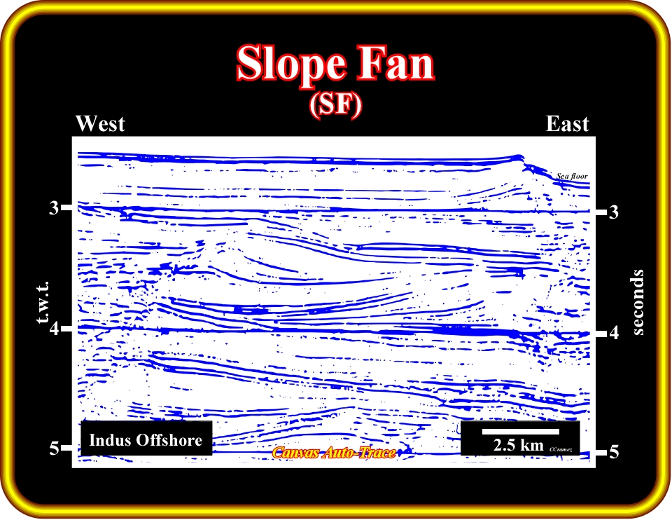
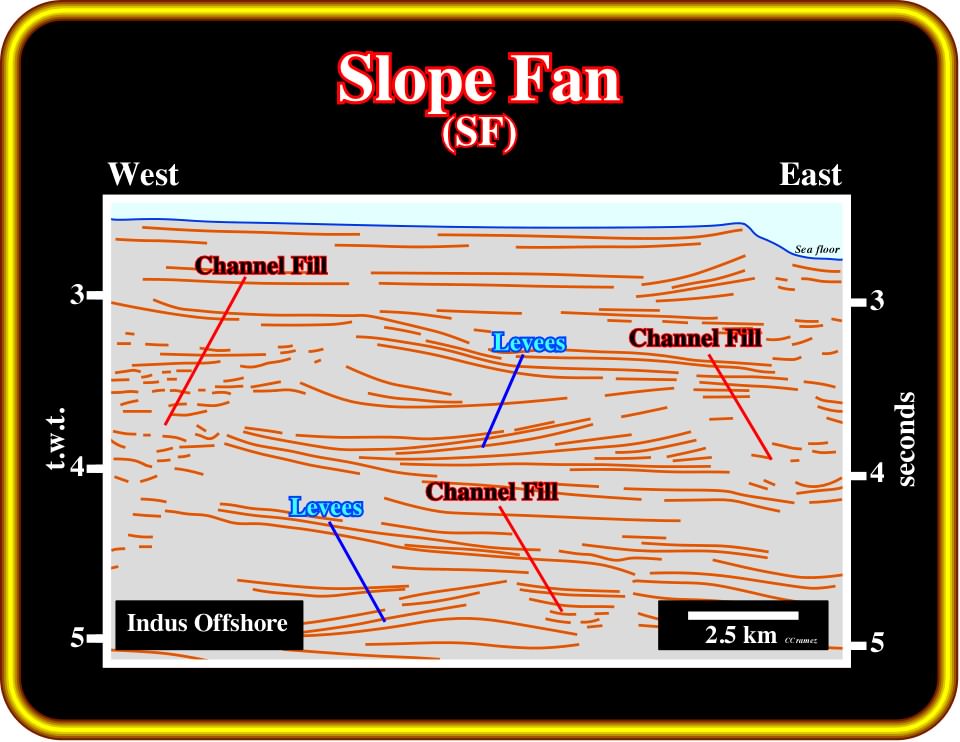
Plate 391- This auto-trace of seismic line from the offshore Indus illustrates, the strike geometry of channel-levee complexes, which are the principal depositional system of a slope fan where potential siliciclastic reservoir-rocks can be found. Outwardly, the presence of sandstone reservoir depends, exclusively, on the lithological composition of the turbiditic currents. In this particular area, the channel-levee complexes are shale prone. Taking into account the geological setting of the shelf and nearby onshore, it is quite logical to assume that the potential turbidite currents will be, mainly, composed by shaly sediments. The absence of differential compaction, particular above the channel fills (filling of the central conduits), strongly, suggests a predominant shaly facies.
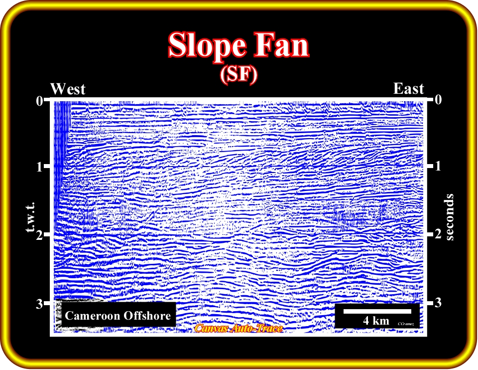
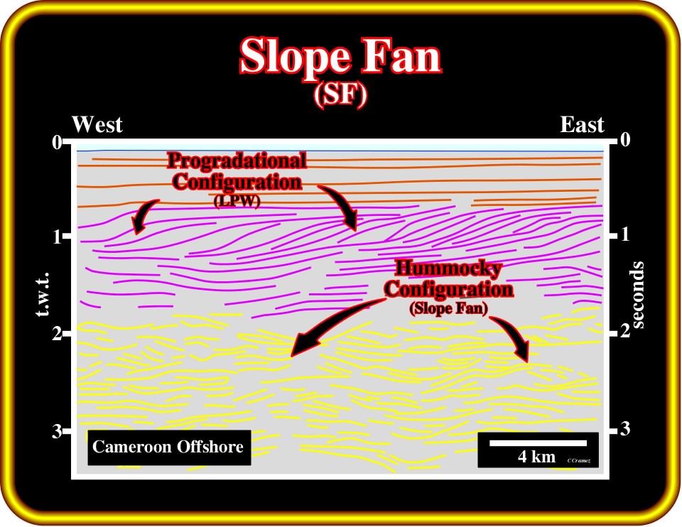
Plate 392 - Channel levee complexes are not always so obvious as in the previous Plates. Very often, as on this tentative interpretation of an auto-trace of seismic line from the offshore Cameroon, the identification of the slope fans is, mainly, based on undulated or hummocky configuration of the seismic reflectors (“gull wings” of P. Vail), which is induced by the over-bank deposits dipping in opposite directions. It is interesting to notice that, in the 80's, the exploration of this offshore was, mainly, based on the drilling of structural traps. At that time, explorationists, even those of the major oil companies were so ignorant in stratigraphy and tectonics, that they took the channel levee complexes as anticline structures. We remember quite well the drilling proposal of Matanda #1, which having found oil in the western flank of a supposed structural trap, forced the explorationists to drill Matanda #2, in the eastern flank, in order to better evaluate the oil reserves. As Matanda #2 found also oil, explorationists advanced quite important reserves. However, a detailed study of the tests, strongly, suggested that the thin sand reservoirs, recognized in both wells, were quite limited and not connected. A short telephone call with a competent geoscientist, knowing quite well turbidite depositional models, that is to say, my friend Emiliano Mutti, was enough to solve the mystery. The anticline structures became turbiditic channel-levee complexes and the huge oil reserves became hydrocarbon indications without economical interest. Similar histories happen with other 'structural prospects”, as Soulebaba, in which at least five wells were drilled before explorationists understood the channel-levee depositional model.
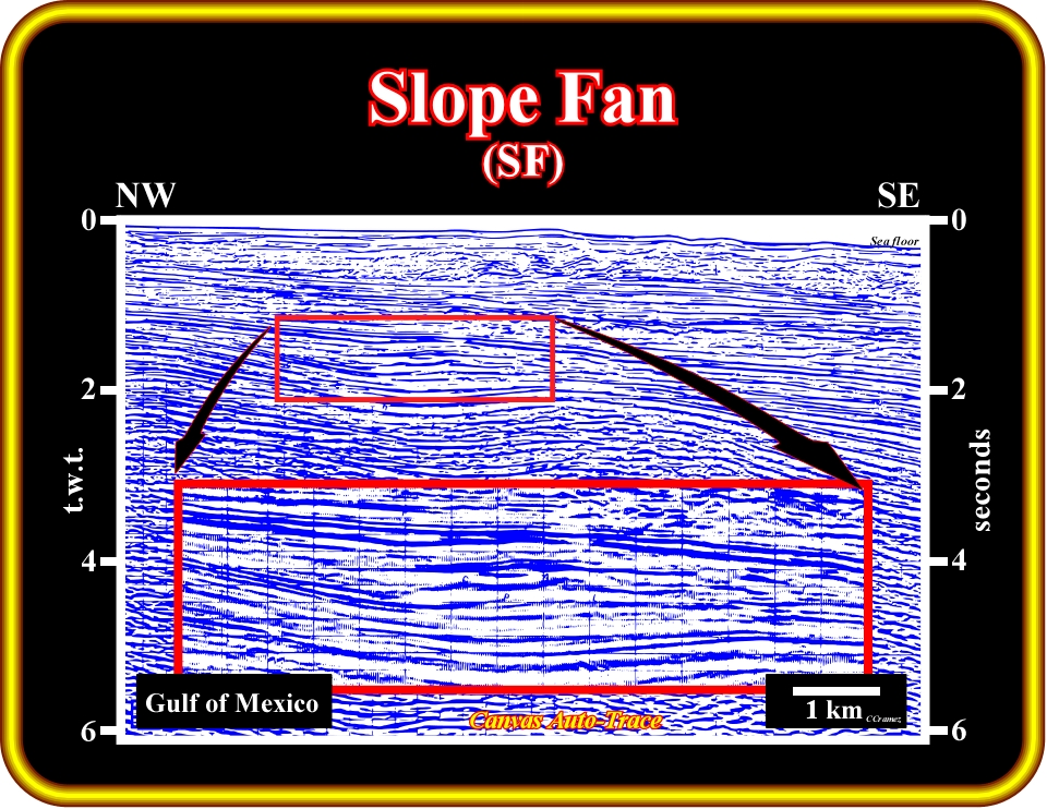
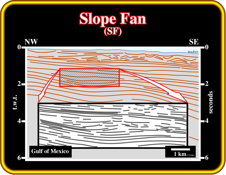
Plate 393 - In the Gulf of Mexico, explorationists are often looking for slope fans and, particularly, channel levee complexes, as potential hydrocarbon reservoirs and traps. In the majority of cases, explorationists identify the potential reservoirs, when seismic anomalies, as bright spots or flat spots, underlie significant hydrocarbon saturation, as illustrated above. However, they forget that only a detailed sequential stratigraphy of the original seismic lines and calibration wells allows the prediction of the actual geometry of such reservoirs, and so the most likely hydrocarbon reserves.
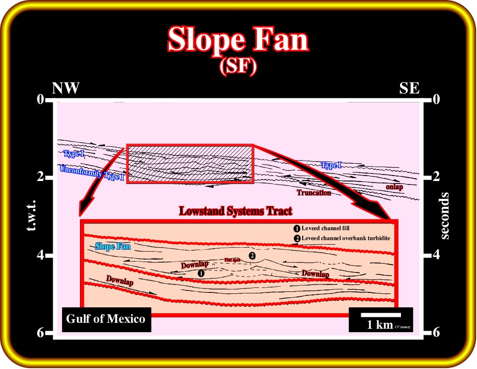
Plate 394 - The geometrical relationships between the chronostratigraphic lines, i.e., the reflection terminations, and seismic surfaces, between 1 and 2.5 seconds of the previous tentative interpretation are depicted. Three sequence-cycle boundaries, associated up-dip with type I unconformities, limit the lowstand systems tracts of two sequence-cycles. The upper one is, mainly, composed by the middle lowstand member (slope fan) in which channel-levee complexes are predominant. In terms of potential hydrocarbon reservoirs, one can say, the most likely are the thin sandstone layers of the over-banks, since the morphology of the central conduit suggests a shaly fill.
Exploration Applications:
1) Reservoir :
- 5-40 meters sands in channels ;
- Channel sands discontinuous ;
- Thin (1-300 cm) sands in over-bank facies ;
- Over-bank sands may be quite widespread ;
- Over-bank sands difficult to recognize and evaluate ;2) Migration :
- Uncertain, probably vertical via fault conduits or from BFF ;
3) Source :
- Uncertain, probably deep ;
4) Trap :
- Typically stratigraphic ;
- Some structural enhanced ;5) Seal :
- Interval shale seals ;
- Top seal: condensed section ;
- Over-bank sands limited by levees and apron-edge pinch-outs ;
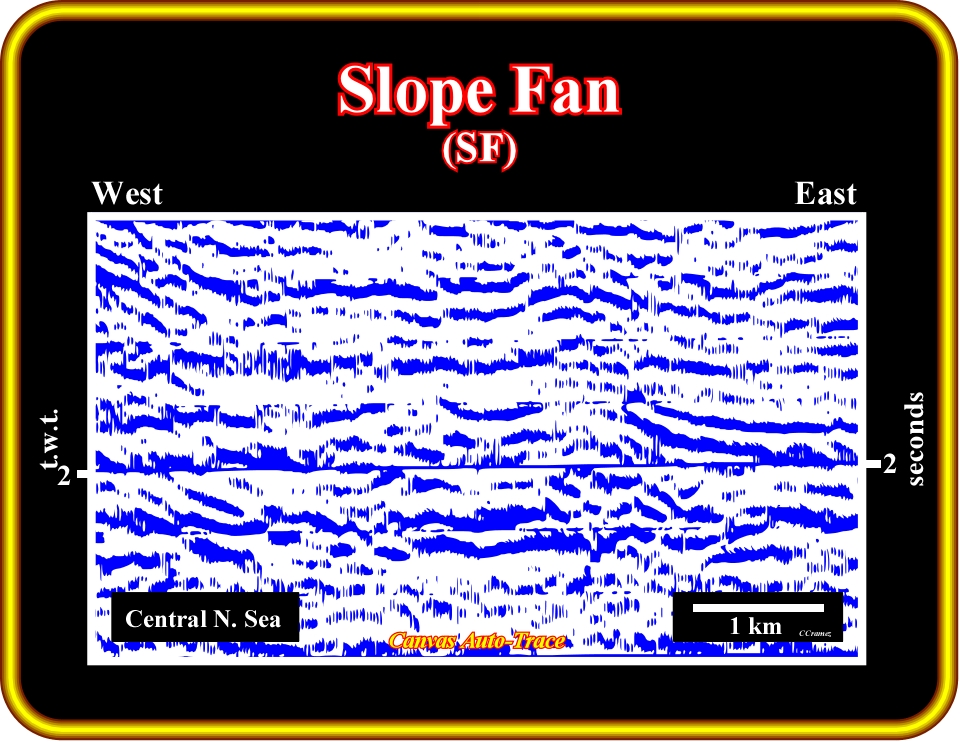
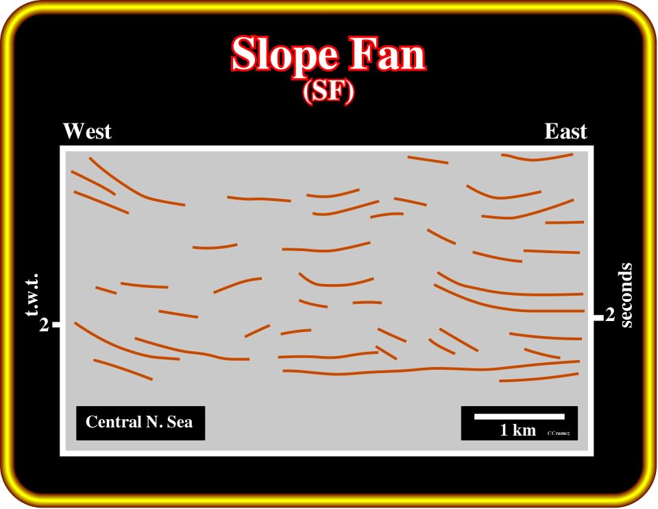
Plate 395- This close-up of a tentative interpretation illustrates the main reservoir interval of a major oil field in the North Sea, in which slope fan sandstone reservoirs are paramount. In this kind of data, it is quite evident that the knowledge of the different depositional models precedes the interpretation (“Theory Precedes Observation”). on this particular example, if the seismic interpreter does not know, a priori, the different depositional models of the lowstand systems tract, he can not understand the migration / entrapment petroleum sub-system, and so, the petroleum system itself. On the contrary, if he knows and understands the depositional systems of the lowstand systems tract, he can propose an interpretation of this close-up similar to the one illustrated on the next plate.
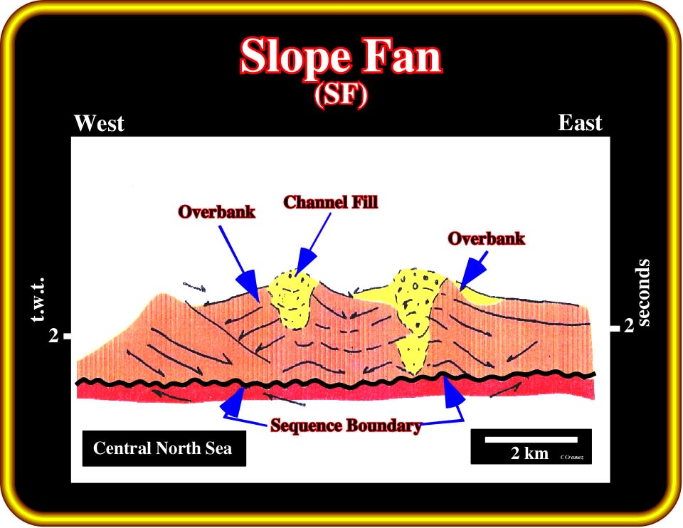
Plate 396- Knowing a priori the depositional model of the slope fan member of a lowstand systems tract, all explorationists, and particularly, seismic interpreters, can, readily recognize, on the previous close-up, the reflections terminations, the seismic surfaces and the most likely location of the potential reservoirs. In fact: (i) the lower sequence boundary, which corresponds up-dip to an unconformity, can be, easily, picked ; (ii) the opposite downlaps of the levees become evident, as well as ; (iii) the channel fills, i.e.,, the filling of the central conduits, which were the pathway of the turbidite currents. Taking into account this interpretation, one can say the main reservoir-rocks of the field (Alba Field) are the sandstones filling the original depression between the over-banks of a slope fan (on this geological context, the term channel can be misleading). On this subject, it is crucial to notice the mounded morphology of the top of the infilled channell, which when explained by differential compaction implies a sand facies.
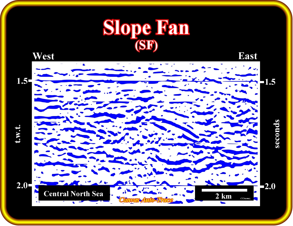
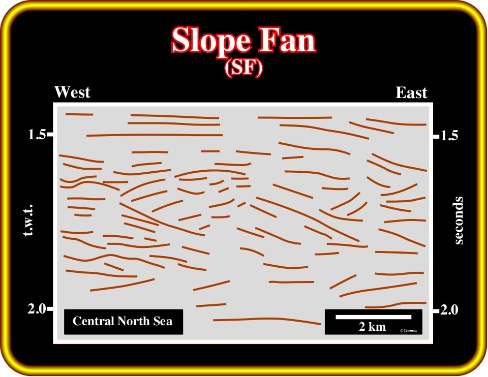
Plate 397- The a priori knowledge of the depositional systems composing the lowstand tract is a "sine qua non" condition to perform a coherent interpretation of the original seismic line from which this auto-trace was taken. Young explorationists and particularly seismic interpreters should not think that an increasing of seismic quality or 3D data can replace geological knowledge. An increasing in quality and definition of seismic data requires a higher increase in the geological knowledge of the interpreter. Knowing the depositional models, taught in all Geological Schools and the regional context of the area, this auto-trace can be interpreted as illustrated in next plate (Plate 398).
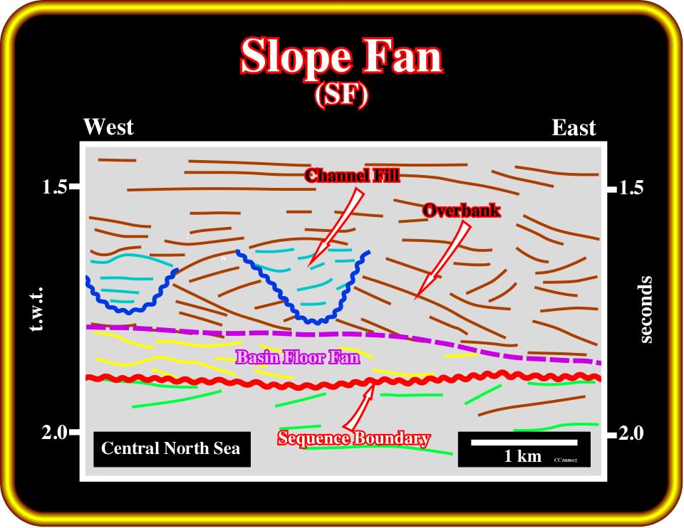
Plate 398- Knowing the regional geological setting of the area, where the seismic line of this auto-trace was shot, and the slope fan depositional models, this auto-trace can be interpreted as illustrated on this tentative interpretation. A lateral coalescence of channel-levee complexes is proposed. The potential reservoirs sandstones are, mainly, associated with a late infilling of the central depression between the over-bank deposits. As turbidite currents have used the central depression as a pathway, they could, slightly, incise it. In any case, the central depression can be interpreted as a submarine valley. Fundamentally, it corresponds to a bypass zone, which is later, i.e., when the relative sea level starts to rise, filled in by backstepping.
Exercises:
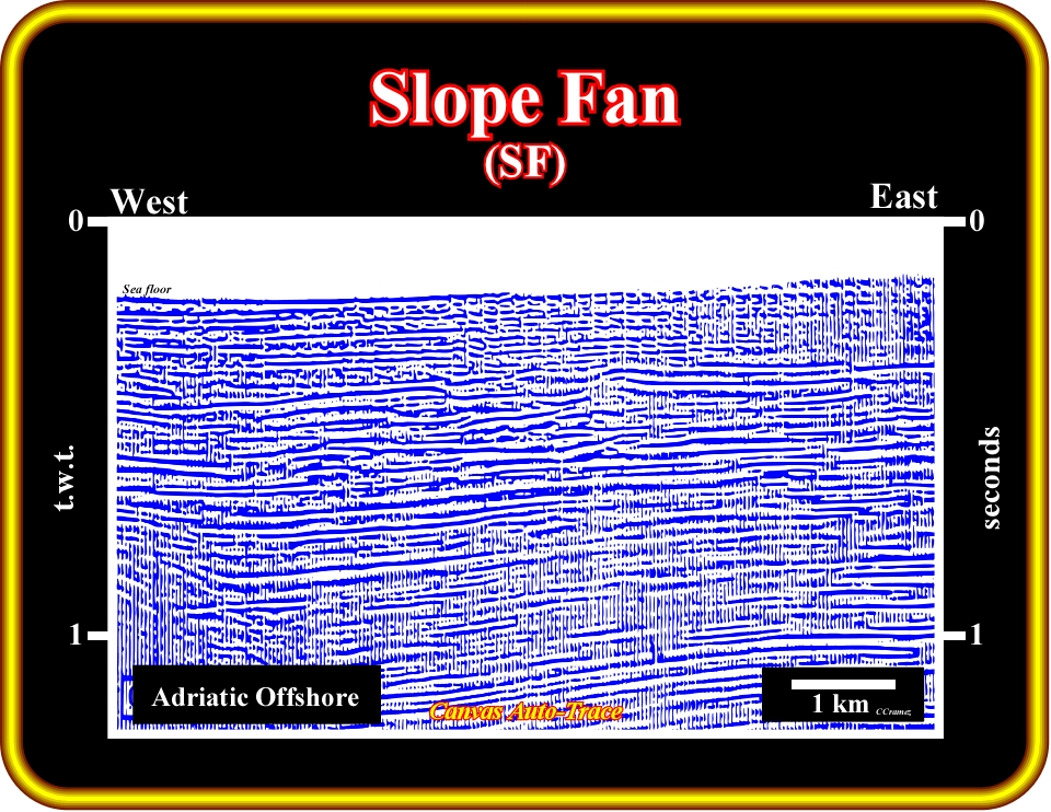
Plate 399- In the Adriatic Sea, slope fan sandstones are, often, the most likely potential reservoirs. Explorationists are obliged to perform sequential seismic interpretation in order to locate them. Propose a sequential interpretation of the upper part of this auto-trace and located the more likely reservoir-rocks.
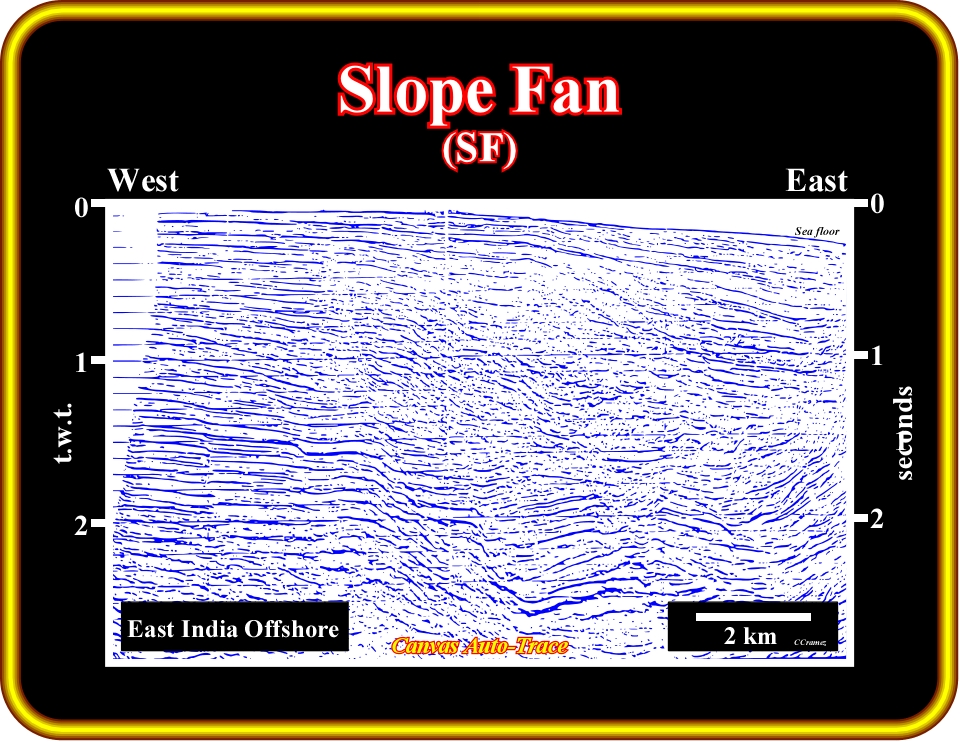
Plate 400- Locate the more evident sequence boundary. Then, locate the major downlap surface, which separates the transgressive package from the regressive package. Then, individualize the most likely lowstand channel-levee complexes and located the potential siliciclastic reservoir-rocks. Finally, assuming a deep generating petroleum sub-system locate an exploration well.
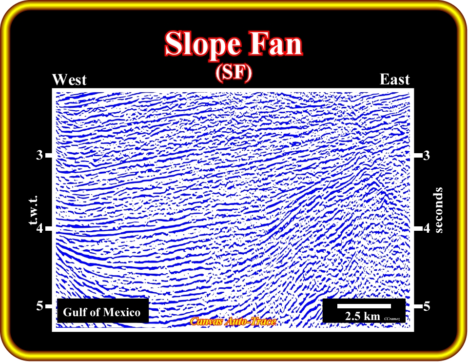
Plate 401- On this auto-trace of a seismic line from the Gulf Coast, there are three evident sequence cycle boundaries. Start by individualizing them, knowing that the upper one is, mainly, characterized by a slight sub-aerial erosion (incised valleys). Then, propose a sequential interpretation of the stratigraphic sequence-cycle bounded by the upper sequence-cycle boundaries, knowing that its transgressive and highstand systems tracts are absent. Finally, locate the most likely potential reservoir-rocks and propose a well location.
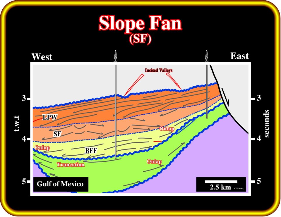
Plate 402- This interpretation is the most likely solution of the previous exercise. The three obvious sequence-cycle boundaries are picked in green. The lower ones are emphasized by onlap seismic surfaces and the upper one by incised valleys. The sequence-cycle between the upper boundaries is composed by a basinal floor fan (BFF), a slope fan (SF) and a lowstand prograding wedge (LPW). The channel-levee complexes are, easily, individualized by their opposite downlaps. The main reservoir-rocks are either the thin sand layer of the over-banks or the basin floor sandstones or the coastal sandstone of the lowstand prograding wedge. Two exploration wells are possible, one targeting the over-bank sandstones (stratigraphic trap) and the basin floor fan (morphological trap), other targeting the coastal sandstones (morphological trap by juxtaposition).
to continue press
