
The sketch below depicts the main characteristics of a regional extension (halokinesis excluded). Take note that:
(i) Extension is the consequence of an extensional tectonic regime, that is to say, a tectonic regime characterized by an ellipsoid of the effective stresses with a σ1 vertical ;
(ii) The only way to extend or lengthen sediments is by normal faulting ;
(iii) Normal faults will strike parallel to σ 2, i.e., they are parallel to the intermediate effective stress (σ2) of the stress ellipsoid.
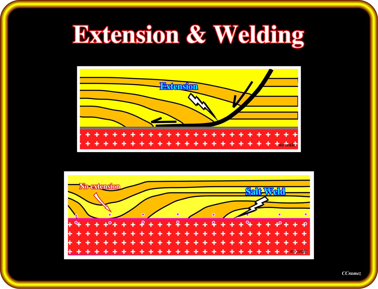
The normal fault dying on a décollement surface, separates the undeformed upthrown block sediments from the extended down-thrown sediments. In a close up, the changes in the dip of the fault plane underline the lithological changes in the up-thrown block sediments. The extension takes place in the downthrown block, where the sediments form a rollover structure, which can be, more or less, be affected by normal faulting. In this particular case, the extension is synkinematic. The sediments show a thickening toward the fault plane. The geological model of a total salt welding, without any regional extension (halokinesis) is, mainly, characterized by an important salt weld, with an apparent downlap surface and significant depocentre (no extension).
(iv) The hade of the normal faults decreases with depth. Faults with such geometry are, often, erroneously called listric normal faults (etymologically, the term listric fault was used to describe a fault not only with a curvilinear cartography but chiefly with normal fault geometry, in the upper part, and reverse fault geometry, in the lower part ; such geometry is typical of the faults created by gliding when the pore pressure becomes big enough). The term listric (from the Greek listron) means shovel ;
(v) The extension takes place only in the downthrown fault block ;
(vi) There is no extension or thickening of the sedimentary interval within the up-thrown block, as illustrated below.
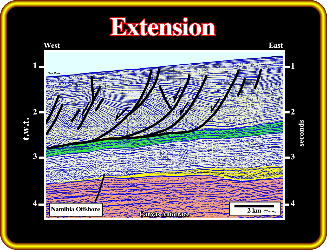
The Plio-Pleistocene sediments of the offshore Namibia are extended upon a detachment surface, which corresponds to a condensed stratigraphic deepwater interval. The extension was synchronous with the sedimentation, as suggested by the landward thickening of the sediments in the downthrown faulted blocks. The normal-faults flatten in the detachment surface. Therefore, their traces in time slices or time contour maps have a curvilinear geometry.
In the before last plate, the depocentre indicated by “no extension”, was created by total salt removal either of a salt roller or a small diapir. It is interesting to notice that in such an extreme case, the surface associated with the top of the salt (surface defined by reflection terminations) disappeared ; it becomes coincident with the salt welding. The geometry of the chronostratigraphic lines can not be interpreted as progradational package, i.e., the geometrical relationships are not downlap, since the thickness between the two consecutive time lines increases progressively toward the discontinuity (a real downlap relationship implies a seaward thinning since the interval becomes condensed down-dip).
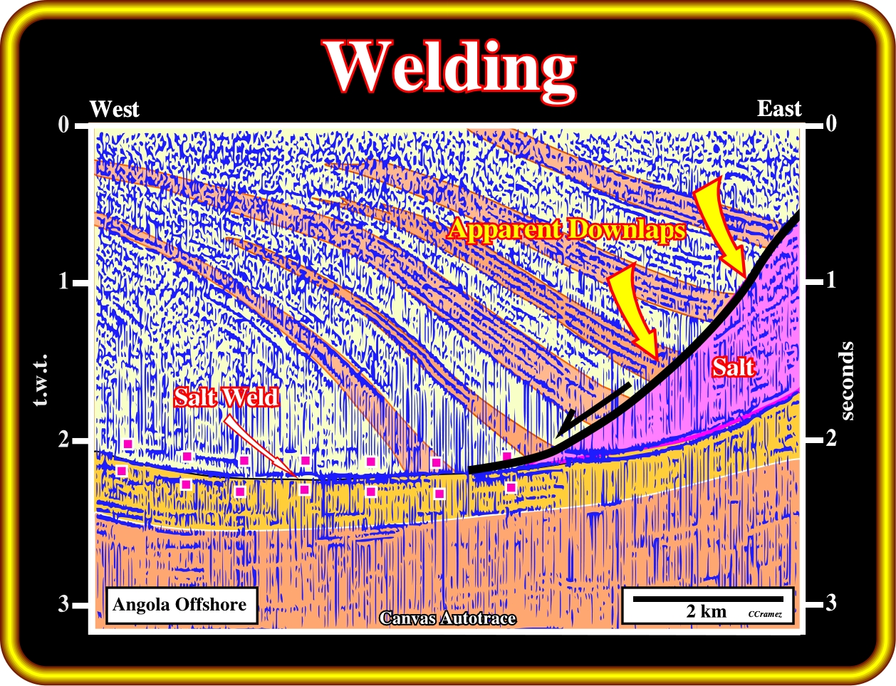
Here, one can say that salt flowage creates a compensatory subsidence and a salt welding. In other words, the apparent downlap surface was induced by a down and basinward gliding of the synkinematic onlapping sedimentary layers, which, naturally, thick against the curvilinear normal growth fault.
A combination of extension and welding is always possible, as illustrated in the next plate.
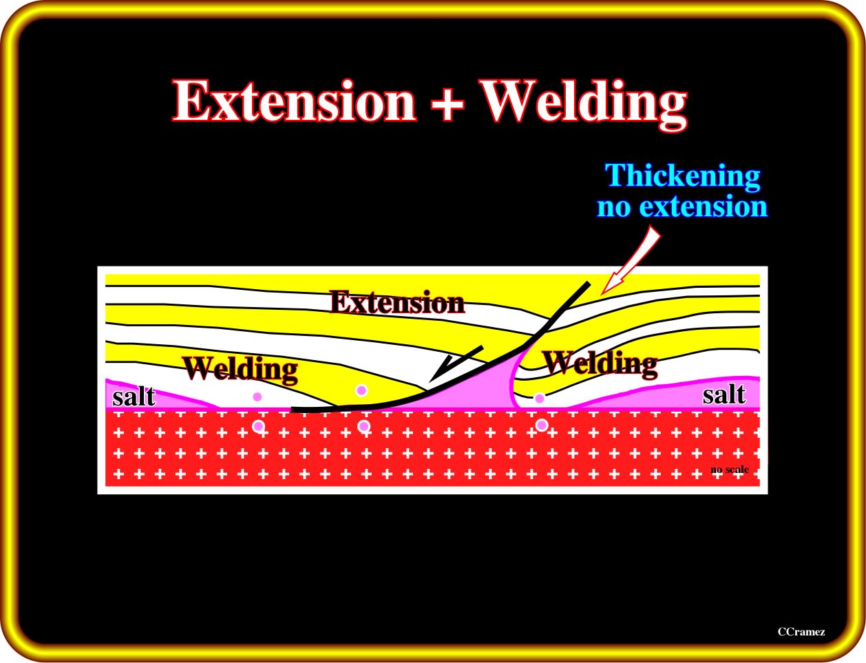
On this sketch are summarized the characteristic geometrical relationships between the chronostratigraphic lines (seismic markers) of a stratigraphic column that had undergone extension and salt welding. In this particular case, the fault plane of the growth fault can be considered as a fault weld, since, in the downthrown faulted block, there is extension and welding, while in the upthrown block only welding takes place.
On the other hand, it must be notice that in both faulted blocks of the above sketch, the stratigraphic intervals thicken toward the fault. On the up-thrown block, the thickening is just due to the withdrawal of the salt. Thereof no major regional extension is associated.
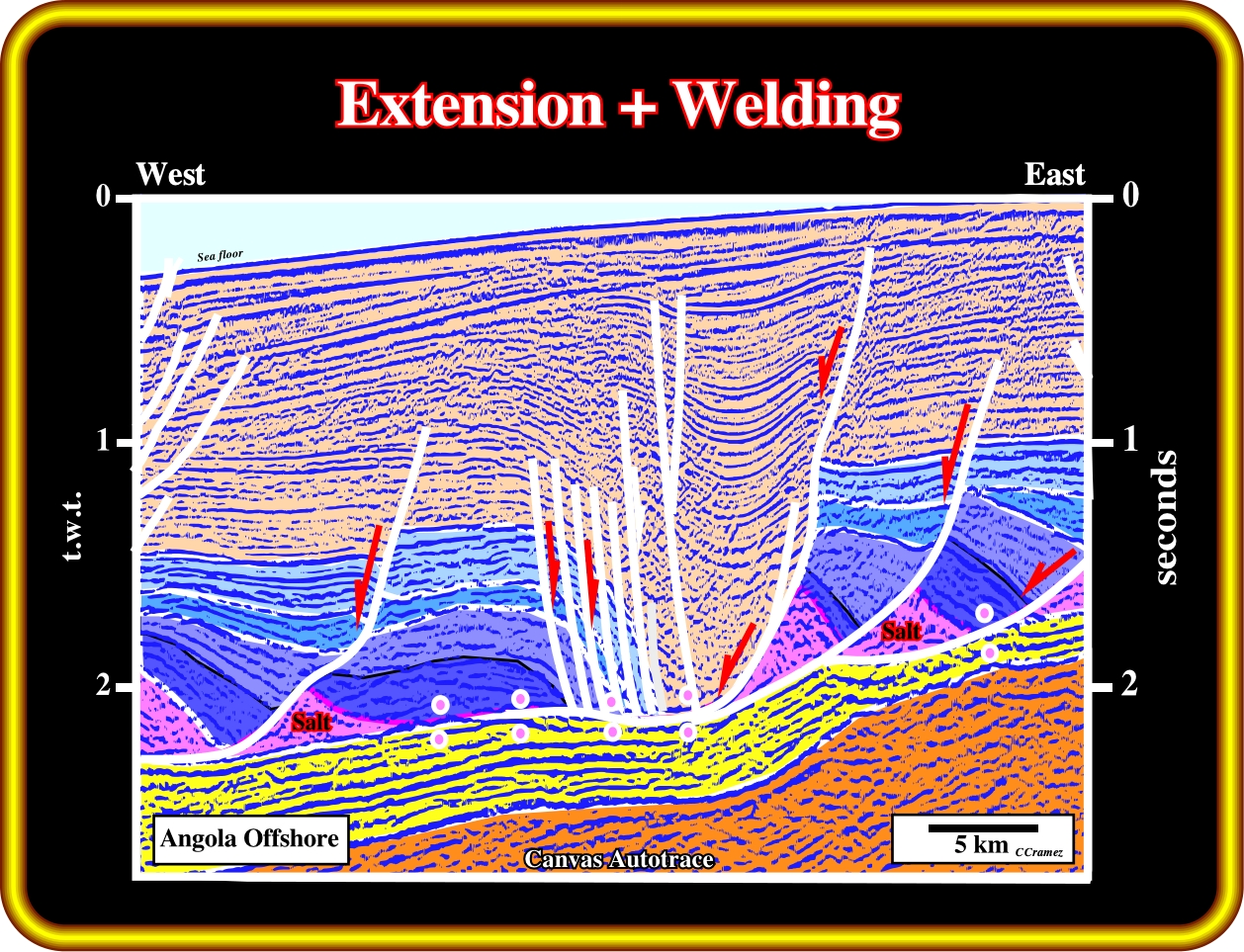
When welding (primary or fault weld) is combined with extension, as illustrated on this geological tentative interpretation of the seismic line from Angola offshore, one should not overestimate the salt reduction (mass transfer of salt over time, see later).
The major differences between:
(i) Extension ;
(ii) Extension + Welding and
(iii) Welding,
are depicted on the next geological sketches:
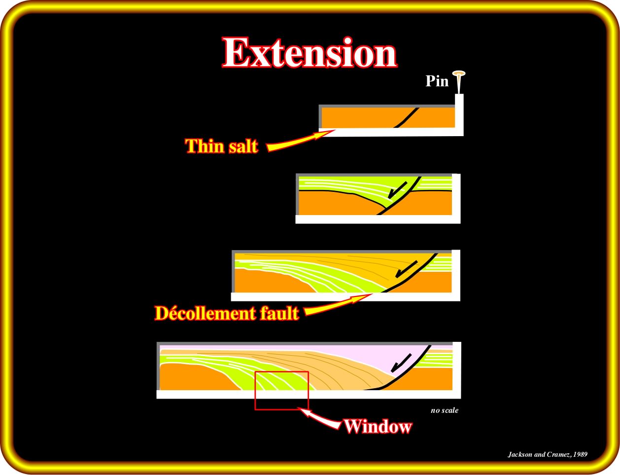
In a pure extension over a thin salt layer or along a décollement surface, as illustrated in this sketch, apparent downlap geometrical relationships (tilted onlaps) are developed against the tectonic disharmony induced by salt flowage, as depicted in the small red window. Take note than in progradtional interval, the thickness between two consecutive progradations, after reach the maximum thickness, becomes smaller and smaller down-dip before become zero.
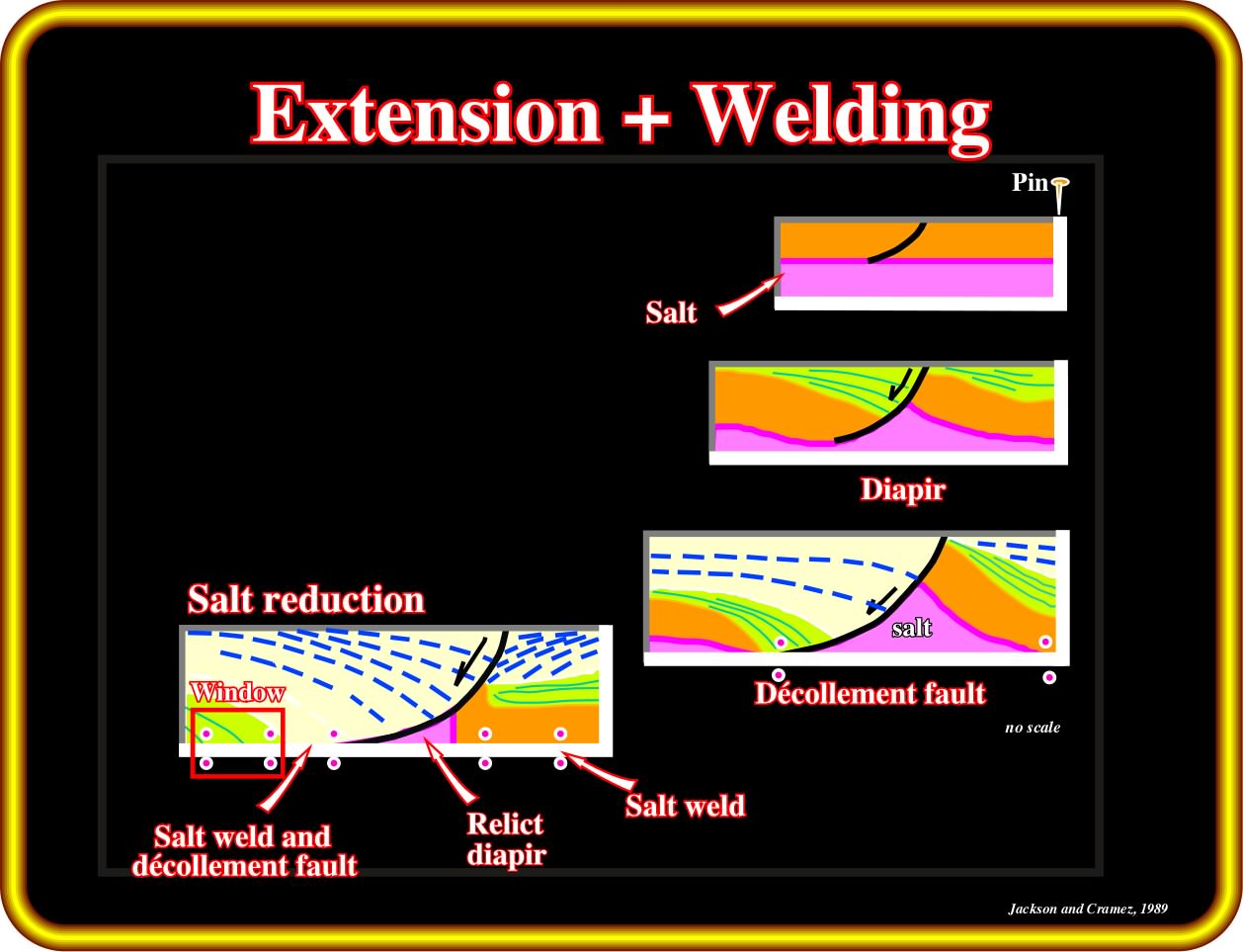
As in the previous plate (extension), apparent downlap geometrical relationships are, also, developed when extension and welding take place. Contrariwise of what happens in Angola onshore (inner Kwanza basin), extension and welding are predominant in Angola offshore, particularly in the outer Kwanza basin.
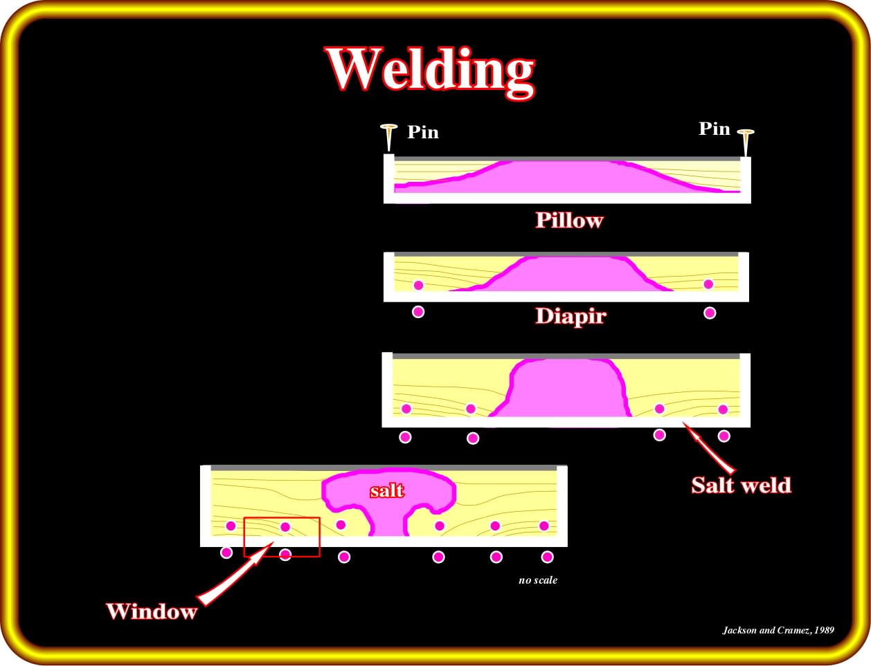
In pure welding (halokinesis), apparent downlaps are also developed in association with the salt weld. Outside of the geological context, it is impossible to differentiate apparent downlap geometrical relationships induced by extension, from those created by extension plus welding or just by welding. Geoscientists cannot work in isolation. On the other hand, geological knowledge cannot progress from the particular to the general. The knowledge of the geological context is fundamental when performing geological tentative interpretations of the seismic lines.
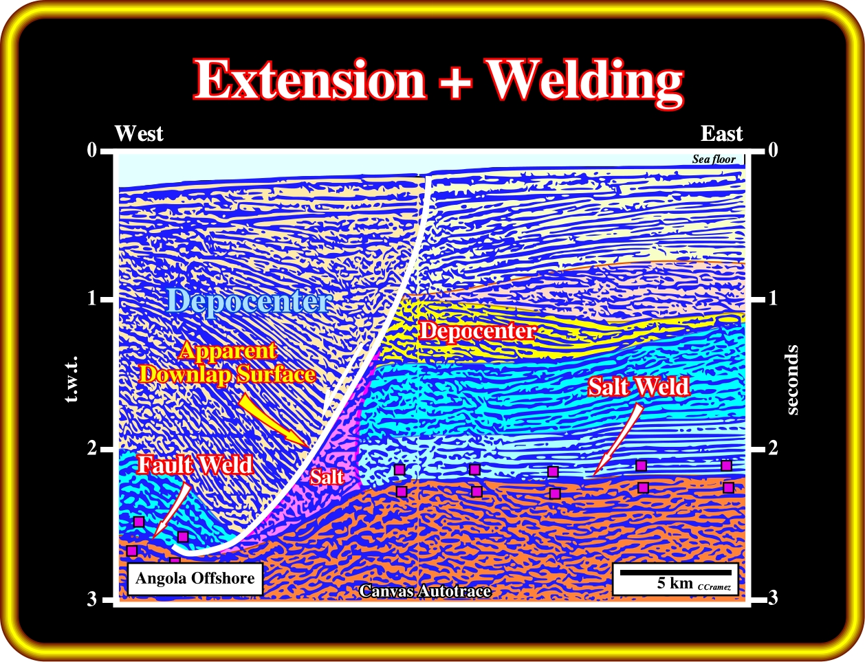
On this geological tentative interpretation of a seismic line from Angola offshore, where the regional geological setting is well known, the geometrical relationships between the seismic markers define seismic surfaces suggesting a regional extension. An extensional tectonic regime and salt welding, mainly induced by halokinesis, exist in the area where this line was shot. A salt weld (halokinesis) is recognized in the up-thrown faulted block. A fault weld (salt tectonics) is recognized in the down-thrown block. Also, (i) an apparent downlap surface and a depocentre thickening toward the fault plane are recognized in the down-thrown faulted block (extension + welding) and (ii) a depocentre, induced by shrinkage of the salt roller, thickening westward is recognized in the up-thrown block (halokinesis).
Exercise 1:
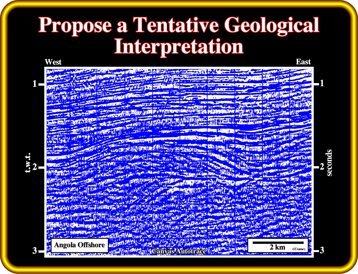
Exercise 2:
(i) The bottom of the salt ;
(ii) The breakup unconformity ;
(iii) A fault weld ;
(iv) An apparent downlap surface ;
(v) Two salt welds ;
(vi) A depocentre in the hanging wall (hangingwall is a synonym of down-thrown fault block, i.e., the faulted block that has a downward relative movement in relation to the up-thrown block or footwall) and a depocentre in the footwall
Finally, you must decide what is the predominant geological processus in the area where this seismic line was shot (extension, welding or both).
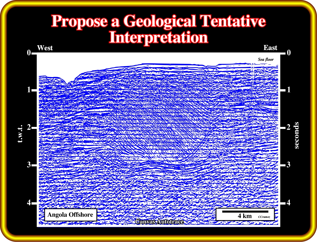
Exercise 3:
Indicate the position of the salt roller (low-amplitude, asymmetric salt structure comprising two flanks: a longer, gently dipping flank in conformable stratigraphic contact with the overburden and a shorter, more-steeply dipping flank in normal-faulted contact with the overburden). After proposing a geological tentative interpretation of this line, explain:
(i) Why are there normal faults at the top of the salt induced antiform (turtle back) ?
(ii) Why in the core of the antiform structure, the seismic intervals thick inward, while in the flanks, they thick outward ?
to continue press
next
![]()