
Three stages of diapirism are often considered:
a) Mounded Stage ;
b) Dome Stage and
c) Post-Dome Stage.

In offshore Alabama (Gulf of Mexico), seaward of the pinchout of the Louan salt, which is emphasized by a graben-like structure, the three stages of diapirism (mounded, dome and post-dome stages) successively recognized.
The differentiation of these different stages of a salt dome evolution is quite important. The petroleum systems and particularly the entrapment-migration petroleum sub-systems are very different from one stage to another. The first two stages, the mound and the dome stages, are well illustrated near the margin of the salt basins (GOM, offshore Alabama, offshore Angola, Mediterranean Sea, etc.). The post-dome stage is easily documented by the salt structures found mainly in the deep water of the salt basins.
a) Mound Stage
The differential subsidence (compensatory subsidence) induced by salt flowage creates:
1) The depocenters around the mound, in which the stratigraphic intervals are thicker ;
2) The uplifted area, where the subsidence is less and therefore where the stratigraphic intervals are thinner.
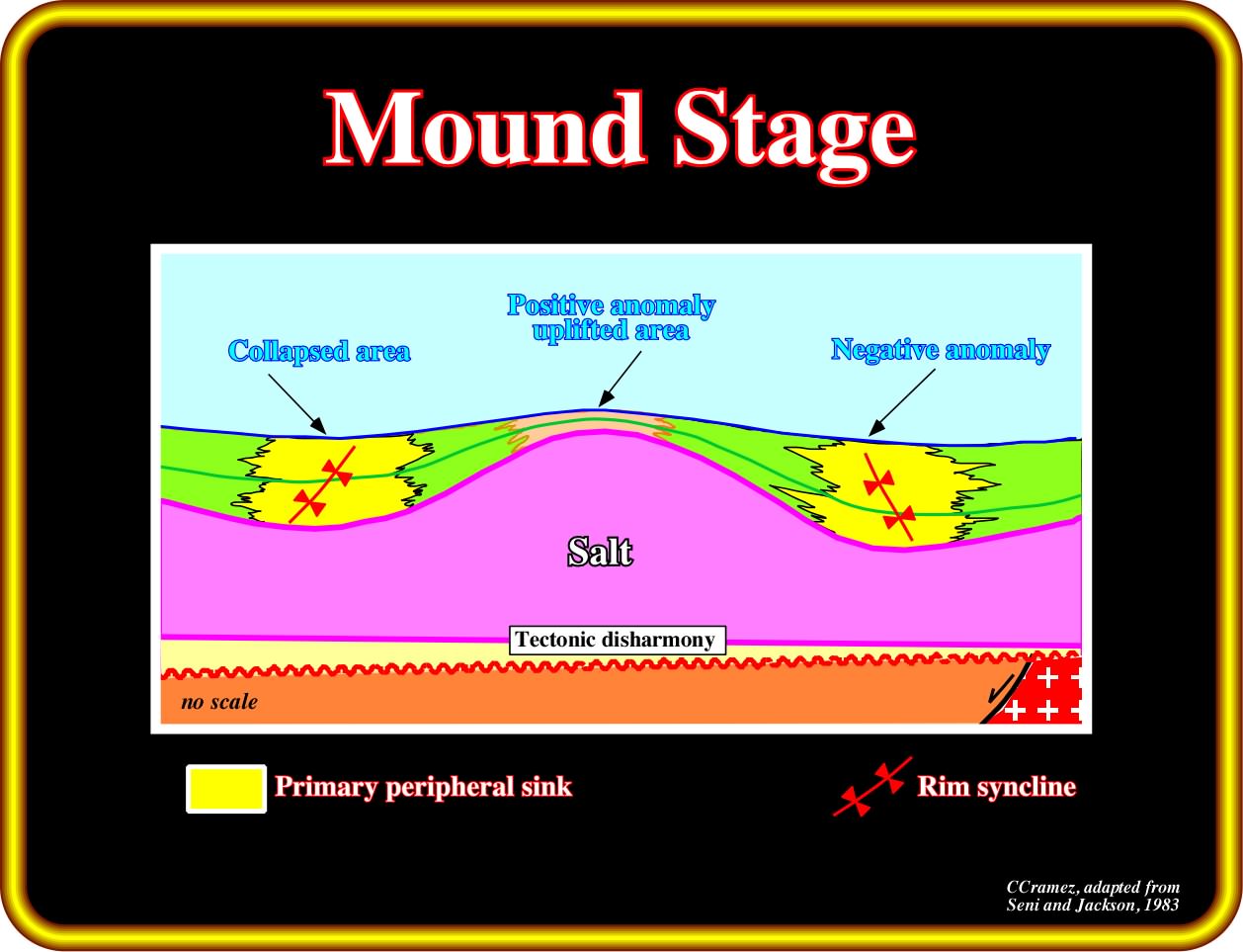
In the mound stage, the coeval overburden interval shows two depocenters on the flanks of the salt mound and relatively condensed stratigraphic section at top the mound. In this sketch, the overburden is synchronous with the salt movement.
b) Dome Stage
The continuation of the salt flowage from the flanks toward the central part of the mound, as the thickness of the overburden increases (depocenters), creates an uplift the apex of the mound forming a dome structure or diapir. The differential subsidence induced by the salt movements creates depocenters in the overburden, in which the central parts are displaced toward the dome. The apex of the dome continues to rise until the salt of the dome will be completely isolated from the mother salt layer. In such a geological situation, the flanks of the mature dome (are almost vertical). However, as said previously, due to the geostatic inversion point, such a sub-vertical geometry is mechanically unstable. With time the unstable dome geometry changes to a stable post-dome geometry.
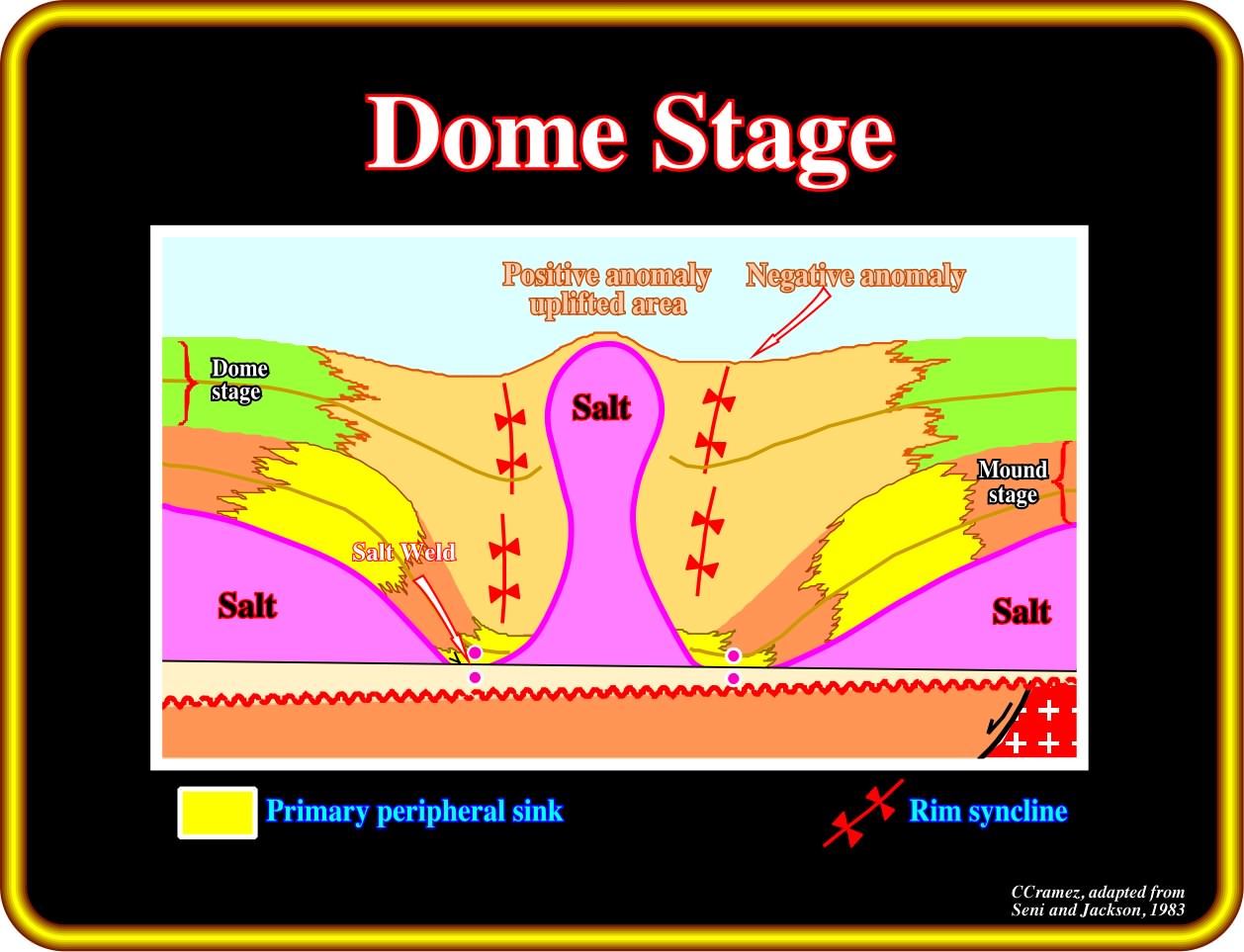
When a salt structure reaches the dome stage, the structure is generally disconnected from the mother salt layer and thick overburden depocentre are developed around the dome. The depocenters developed during the mound stage are, generally located outward of those associated with the dome stage. In other words, the depocenters migrate toward the flanks of the dome.
c) Post-Dome Stage
When a salt dome becomes disconnected from the mother salt layer, it cannot grow anymore. As, the nearly vertical geometry of the flank is an unstable mechanical situation:
- Below the geostatic inversion point, the lateral pressure of overburden against the salt is not balanced by the pressure the salt against the overburden. The salt of the lower part of the dome flows upward ;
- Above the inversion point, the salt lateral pressure against the overburden is not compensated by the one induced by the overburden against the salt. The salt flows laterally toward the overburden creating overhang structures ;
- If the difference between the confinement pressures below the inversion point is big enough, the dome can be disconnected from its root creating a drop structure similar to the one illustrated below ;
- The lateral flow of the salt in the upper part of the dome creates morphological traps by juxtaposition that may be favourable petroleum exploration.
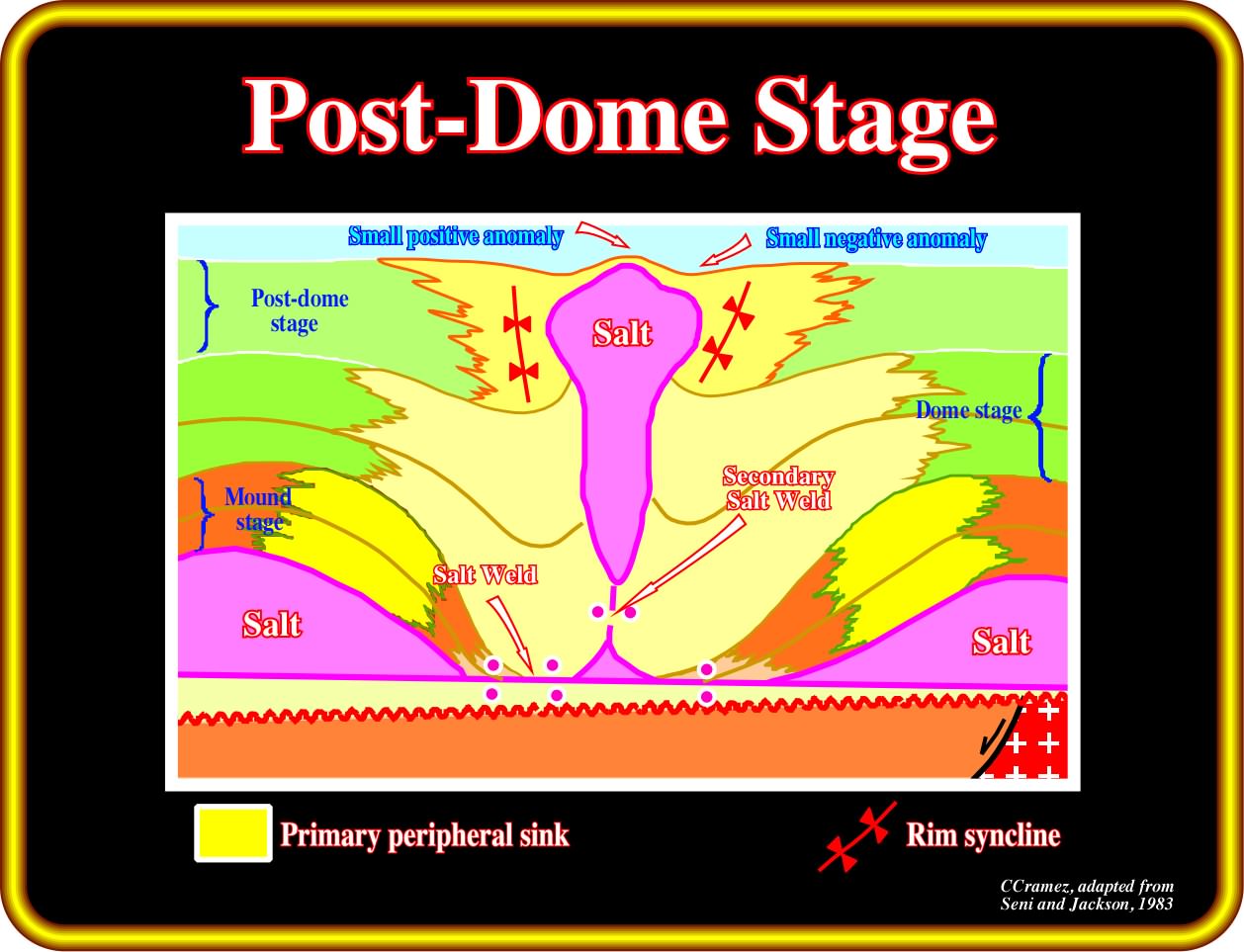
The displacement of the depocenters toward the dome underlines the direction of increasing of the compensatory subsidence. Generally, in a post-dome stage, there is formation of two horizontal and one vertical salt welds. On the sea floor, a negative bathymetry anomaly surrounds a positive anomaly located just above the top of the salt structure.
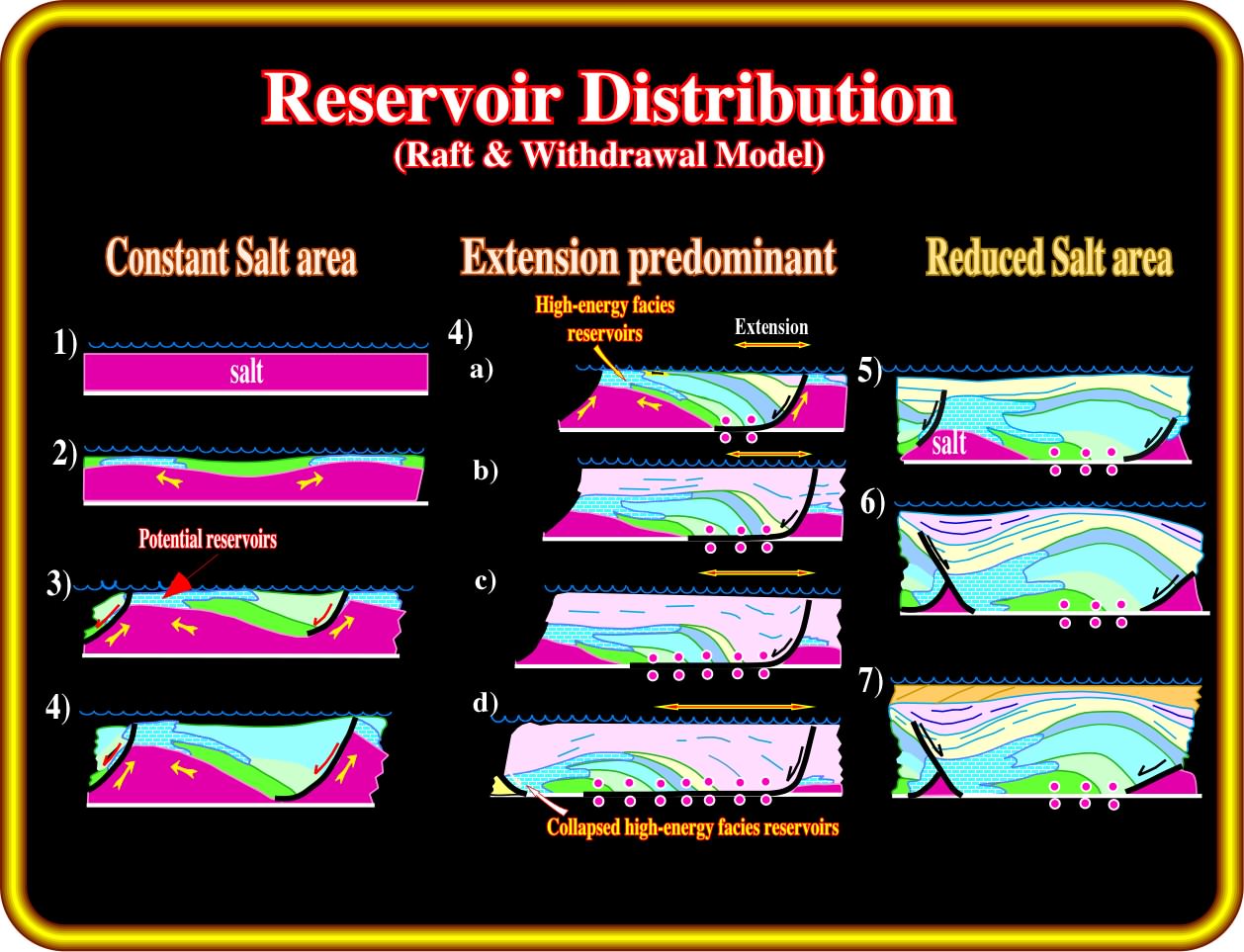
As illustrated below, in sand-shale intervals, some possible reservoir and trap distributions are possible :
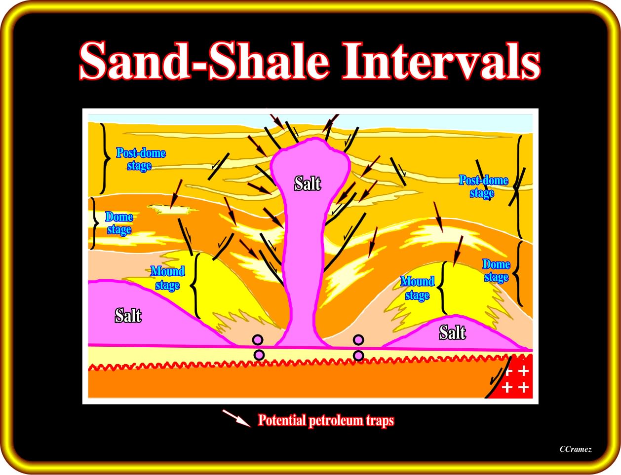
This sketch illustrates the three diapiric stages of an upward salt flowage and the location of the more likely reservoir-entrapment petroleum subsystem, in a sand-shale geological setting.
-The reservoirs are generally located in the areas of maximum subsidence, where accommodation, or available space for sedimentation is higher :
- The traps are mainly non-structural. They are stratigraphic or morphological.
- Structural traps (four way dips) are possible, when the apexes of the turtle-back structures, particularly those of the mound and dome stages, are not faulted. However, such a tectonic situation is rare. Turtle backs are extensional and not compressional structures. Normal faulting lengthens the highest areas of a turtleback structure. Therefore the traps are morphological by juxtaposition (a fault-trap is a misnomer. A fault trap does not exist. A fault never traps. What can trap is a sealing rock in the other side of the fault when juxtaposed to a reservoir rock).
In carbonate intervals, the more likely locations of the potential reservoirs and traps are quite different than those in a sand-shale interval, as illustrated below.
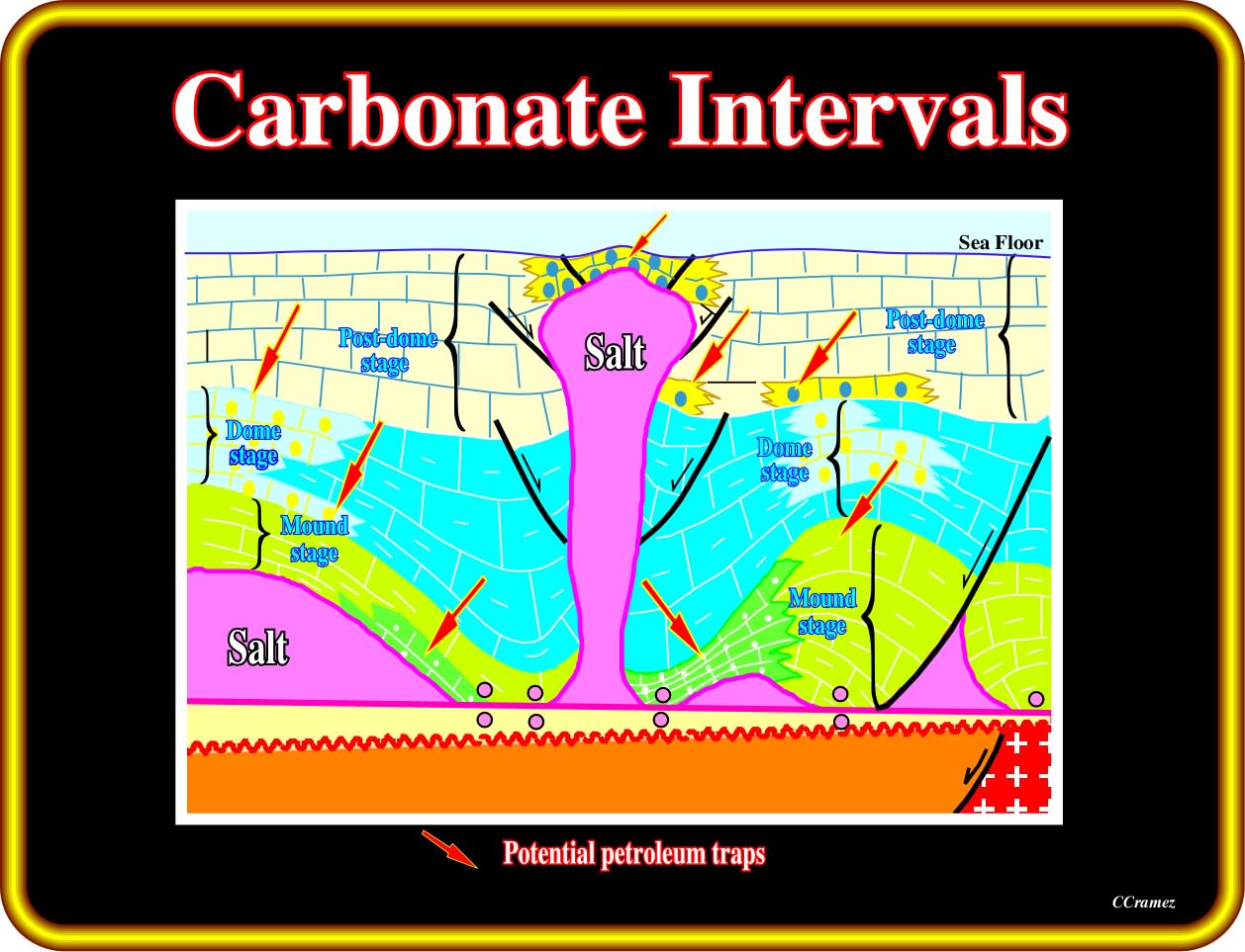
When a carbonate interval is synchronous with salt flowage, the more likely location of the potential reservoirs and traps depends on the water paleo-bathymetric depth created by the compensatory subsidence. Shallow water depth induces high-energy depositional environments, in which reservoirs are likely. Therefore, the potential reservoirs are generally associated with thinner stratigraphic intervals.
-The potential carbonate reservoirs are mainly high-energy deposits, where carbonate production is greater ;
-The more likely traps are non-structural:
a) Stratigraphic and morphological by juxtaposition traps (the trap classification used in these notes, and particularly the term « morphological traps by juxtaposition » clearly indicates the mapping of the sealing rock, which defines the closed area, is as important as the mapping of the reservoir. Without the map of the sealing rock, it is impossible to define a morphological trap, particularly when the morphology is related to a fault escarpment) are by far the more frequent ;
b) Due to salt withdrawal, some of the stratigraphic traps are located on the flanks of structural lows (tectonic inversion). In the Angola conventional offshore , several well-known oil fields are associated with this kind of tectonic inversion ;
c) Structural traps, that is to say, traps with four way dip closure, when present (between two normal faults), are generally too small to accumulate economic amounts of hydrocarbons. The reservoirs when present are quite restricted and their petrophysical characteristics are mediocre.
In 1984 Total’s geoscientists proposed these kind of tectonic inversion induced by salt withdrawal to explain the structures and the reservoir facies distribution of the Pinda formation Angola (plate below). This model (raft tectonics) was proposed as an alternative to the “shoal model”, which had been systematically refuted by the exploratory wells. In salt withdrawal model, the carbonate reservoirs are mainly controlled by halokinesis. Carbonate reservoir facies are deposited over the Loeme salt structural highs. However, following salt withdrawals and lateral salt flowage, structural inversions take place and the initial structural high areas become structural lows (e.g. Lombo East #1, Tubarão #1, Sulele #1, etc.).
Total’s geologists proposed raft-tectonics with salt withdrawal to explain structures and reservoirs facies distribution of the Pinda formation in block 2 (Angola offshore). Roughly, in the raft tectonic model, the carbonate sedimentation is mainly controlled by the halokinesis thereby the reservoir facies are deposited over the Loeme salt structural highs. However, due to salt withdrawals and lateral salt flowage, structural inversions are formed and the initial structural high areas become structural lows. The success of this salt tectonic model was mainly associated with the discoveries of Lombo East, Tubarão, Sulele, etc.. Nevertheless, since then the model could not explain all Pinda structures and reservoir distribution. It was partially refuted by new geological and geophysical observed data.
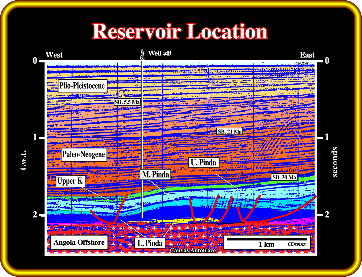
The reservoir location in Sulele West follows the raft and withdrawal model depicted in the previous plate. The Middle Pinda interval progressively thins westward. Such thinning correlates with an increasing of the reservoir qualities of the high-energy carbonates. Eastward, where all Pinda intervals become thicker there are no reservoirs. Therefore, the trapping mechanism is mainly stratigraphic.
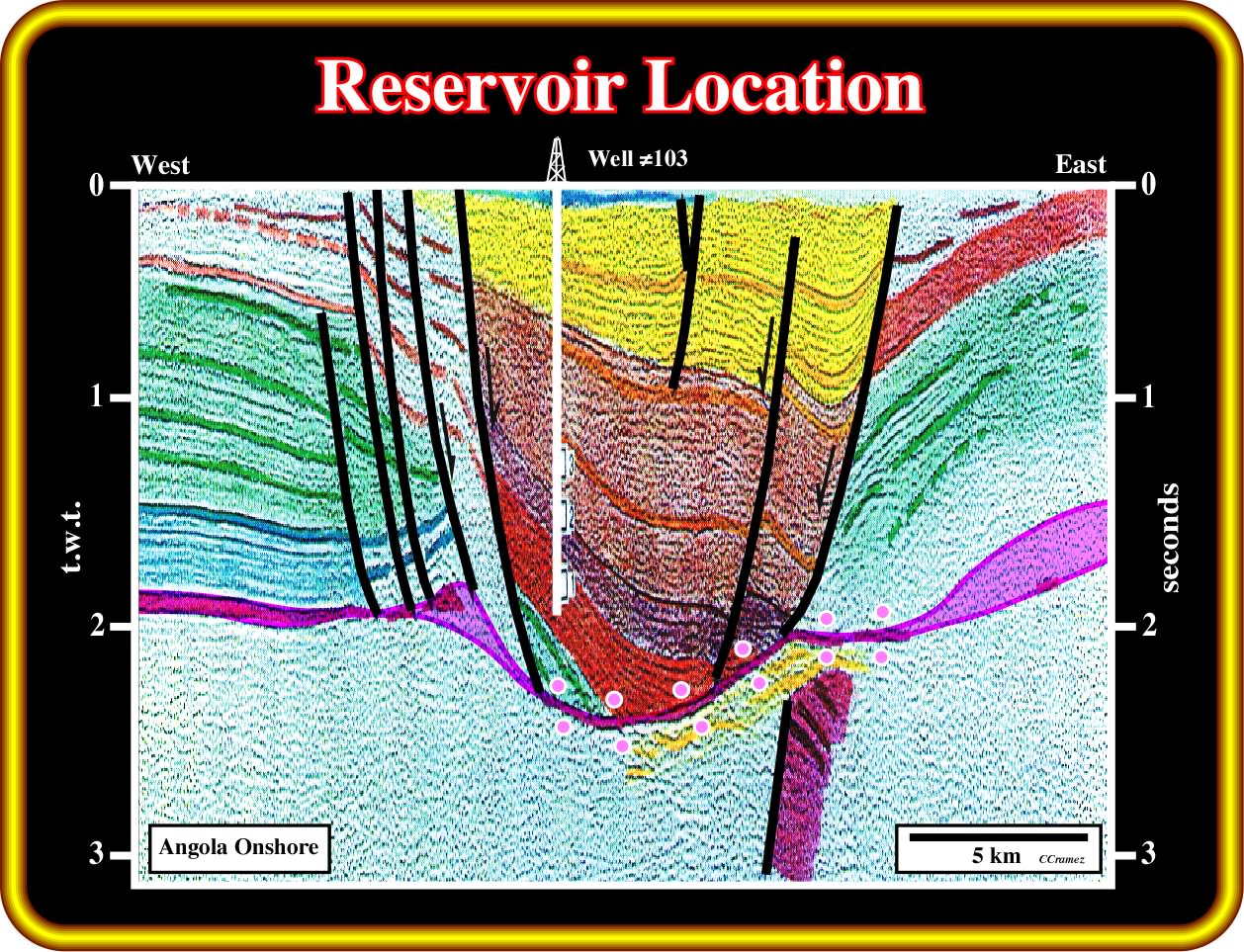
The well 103 (Benza Quitel #1) illustrates the case of a sand-shale interval deposited during salt flowage. The reservoirs are thicker toward the NE fault, where the compensatory subsidence was higher. Again, the trapping mechanism is mainly stratigraphic. The sandstone reservoirs pinch out up-dip.
Exercise 1:
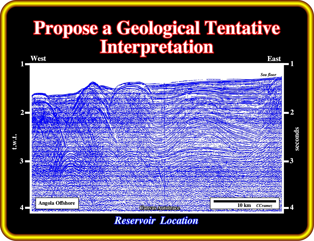
As you probably noticed, this seismic line (Sefel, 1968) is unmigrated. Nevertheless, it is quite rich in geological informations. You probably known the name of the huge antiform structure located in the left of the line. Yes, it is Girassol, know since 1968, when the drilling technology was inadequate to drill under 1.4 seconds (t.w.t.) of water depth such a huge turtle back. Taking into account, that the lower supra-salt interval as a carbonate facies and the upper interval has a sand-shale facies, located the position of the more likely potential reservoir.
Exercise 2:
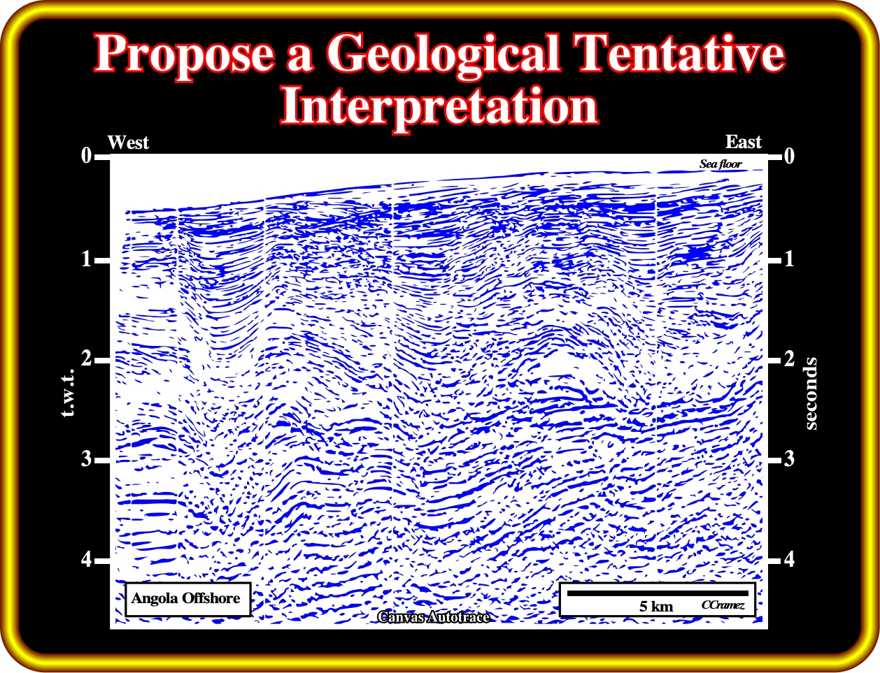
In your tentative interpretation, you must pick:
(i) The top of the basement ;
(ii) The more likely breakup unconformity ;
(iii) The rift-type basins ;
(iv) The bottom of the salt and or the associated primary salt welds ;
(v) The supra-salt antiform structures.
Finally, you must located the more likely potential source-rocks and potential reservoir rocks, justifying their location.
to continue press
next
![]()