Part I- Basic Principles in Salt Tectonics
3.11.5- Allochthonous Salt and Extension
The sketch illustrated in fig. 131, shows one of the possible mechanisms of emplacement of allochthonous salt. In this hypothesis several steps are considered:
a) Extrusive Salt Wall
b) Growth Faulting:
- The extension created by the fault heave of a growth-fault is balanced by shrinking of the stem of the salt wall.
- The shortening due to reduction of the stem induces the salt to flow up-dip and down-dip forming a salt tongue.
- As the shortening of the stem balances the lengthening, due to the fault heave, there is no extension.
c) Salt Welding
-With the continuation of the growth-fault displacement the shrinking of the salt wall stem is complete. The salt tongue will be disconnected from the mother salt layer and the stem will become a salt weld.
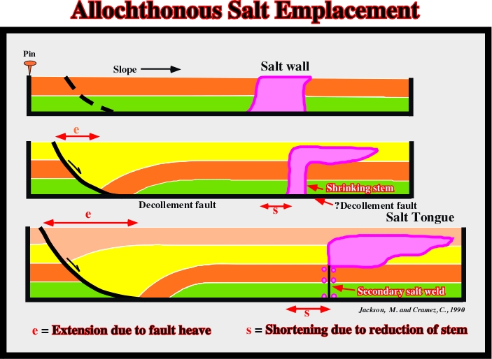
When the extension induced by the growth-fault displacement cannot be balanced by shrinking of the stem, there is a local sedimentary lengthening.
3.11.6- Salt Intrusion Mechanisms
The following figures (fig. 132 & 133) illustrate the principal mechanics invoked to explain salt intrusions.
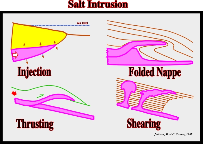
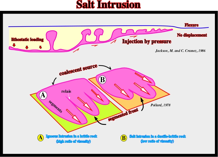
Fig. 133- AS illustrated, the injection by pressure is, mainly, function of the lithostatic loading. In the ground or in a time slice, it is often possible to observe the frontal morphology of the salt intrusions proposed by Pollard for the igneous intrusions. Pollard proposed two hypotheses: (i) Intrusion in brittle rock (high ratio of viscosity), in which the front of injection is asymmetric intrusion and different segments are individualized by long relaid zones and (ii) Intrusion in ductile-brittle rocks (low ratio of viscosity), in which the injection front is rather symmetric and the the intrusion segments separated by individualized by small relais zones.
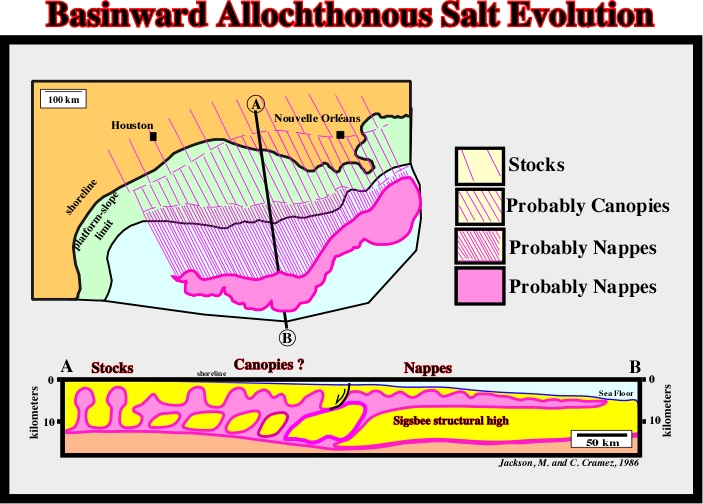
3.11.7- Basinward Evolution of Allochthonous Salt
Allochthonous salt is found in the majority of the sedimentary provinces with a significant salt layer, such as Gulf of Mexico, Angola offshore, Brazil offshore, etc. In these provinces , as illustrated in fig. 136, the allochthonous salt seems to evolve basinward. Indeed, seaward, the predominant salt structures seem to be: (i) Salt stocks (ii) Salt canopies (iii) Salt nappes or Salt sheets.
3.11.8- Allochthonous Salt in the Gulf of Mexico
Petroleum geoscientists working in Gulf of Mexico know how important concept of allochthonous salt is for petroleum exploration. Two perpendicular regional seismic lines (location map in fig. 135), showing large reactivated allochthonous salt sheets are illustrated fig. 136 and 137.
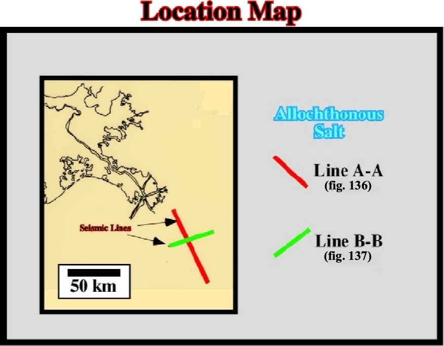
Fig. 135- As illustrated on this location map, the perpendicular seismic lines A and B of the next tentative geological interpretations (fig. 136 and 137) are located seaward of the present time Mississippi mouth.
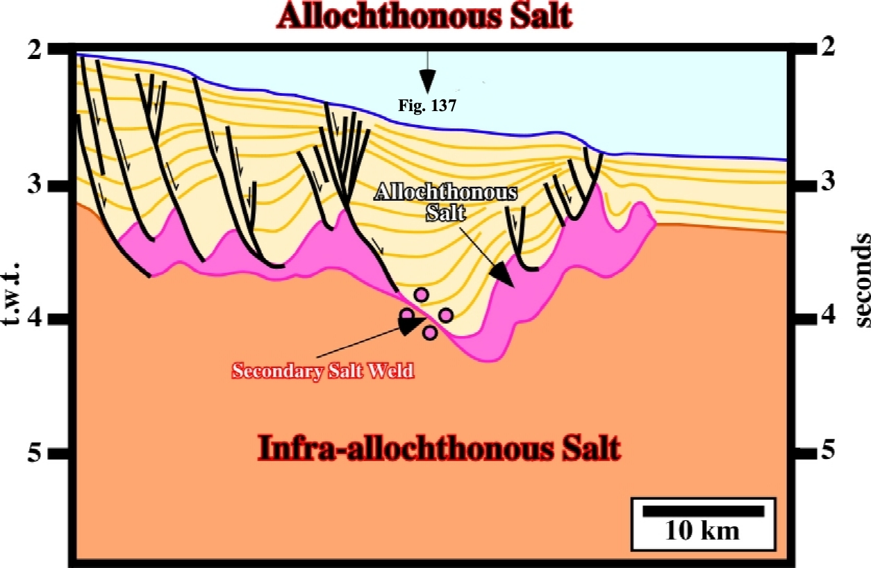
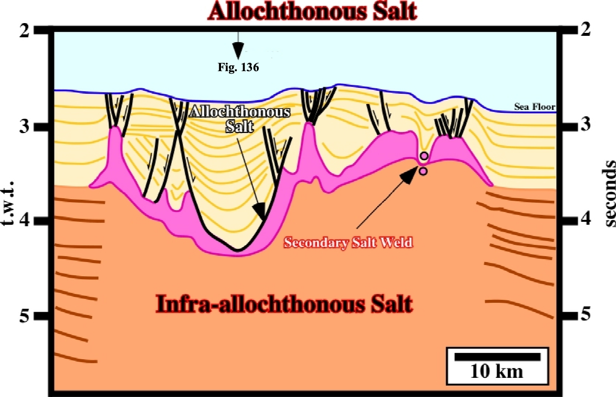
Fig. 137- On tentative interpretation of the perpendicular strike line , the transverse geological section of the reactivated salt tongue is clearly depicted. The down-dip salt flowage, within the salt tongue, created a large depocenter, which strongly contrasts with the “normal” stratigraphy recognized outside of the tongue on the ends of the line.
to continue press
next
. ![]()
Send E-mails to carloscramez@gmail.com or to carlos.cramez@bluewin.ch with comments and suggestions to improve these notes.
Copyright © 2001 Ccramez, Switzerland
Last update: August 2014, May 2022