Part I- Basic Principles in Salt Tectonics
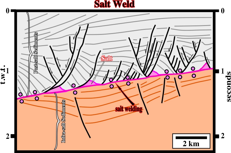
Contents:6.1- Concept of Salt Welding 6.2- Types of Salt Welding 6.2.1- Primary Welds 6.2.2- Secondary Welds 6.2.3- Tertiary Welds 6.3- Recognition of Salt Welds 6.4- Salt Weld and Fault Weld 6.5- Translation Onlap SurfacesA salt weld is a surface separating two stratal units formerly separately by salt and now in contact, as illustrated in fig. 180.
There are three types of salt welds:
(i) Primary Welds, (ii) Secondary Welds and (iii) Tertiary Welds
Primary welds join strata originally separated by autochthonous salt (fig. 181). The salt welds are, generally, gently dipping. Joining regional dipping sub-salt strata with supra-salt sediments (overburden), which, locally, dip more steeply, creates a tectonic disharmony, which may look like an angular unconformity (fig. 182). Dip is, locally, enhanced by rotation due either to listric faulting or salt withdrawal below lapouts. Pitfalls produced by this process are: (i) Apparent downlaps (fig. 183 and 184) and (ii) Pseudo-turtle back structures (fig. 185 and 186). The associated disconformity is enhanced by rotation of the overburden creating apparent downlaps. The original onlaps are tilted, generally, landward as salt withdrawal.
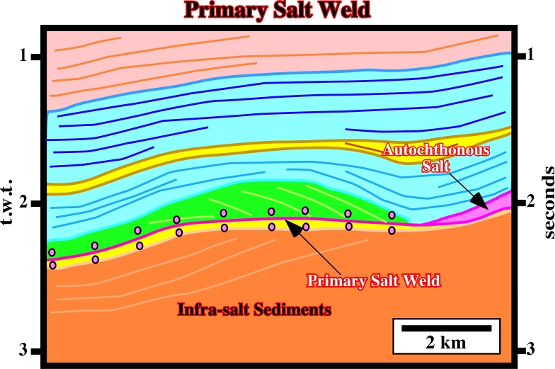
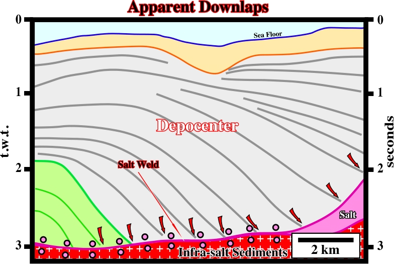
Fig. 182- On this tentative interpretation (Angola offshore), the salt weld, created by the salt withdrawal of autochthonous salt, is highlighted by the small pink circles. On the right side of the tentative interpretation, autochthonous salt is seismically present. At the bottom of the overburden, the pristine onlap geometry of the seismic markers was deformed into apparent downlap reflection terminations due to down-dip salt flowage. This tentative interpretation shows clearly the difference between the salt induced tectoni9c unconformity (bottom of the salt) and the breakup unconformity, which is located at the bottom of the infra-salt margin sediments, i.e., at the bottom of the yellow seismic interval.
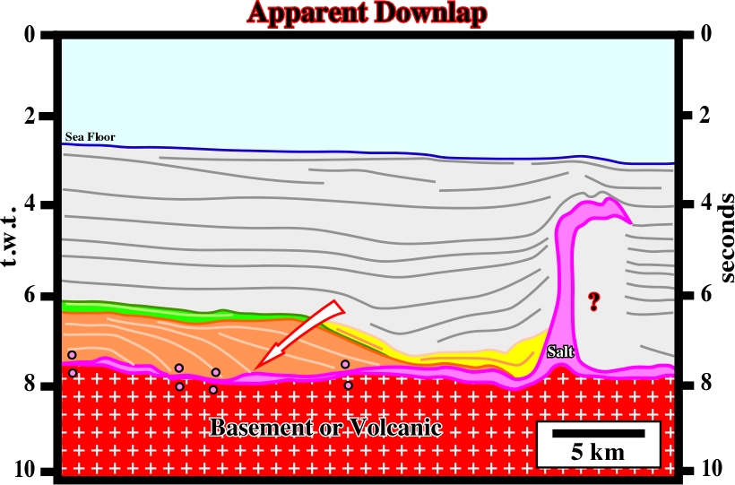
Fig. 183- On this tentative interpretation of a seismic line of Gulf of Mexico, the brown interval does not correspond to a progradational sedimentary package. The refection terminations do not define a downlap seismic surface. The seismic markers were deformed, and tilted eastward (seaward) due to salt flowage, which is also responsible for the allochthonous salt structure visible on the right side of the line. In the 80’s, the majority of the geoscientists working in the GOM interpreted the seismic reflectors within the brown interval as the seaward progradation of the Cretaceous shelf break.
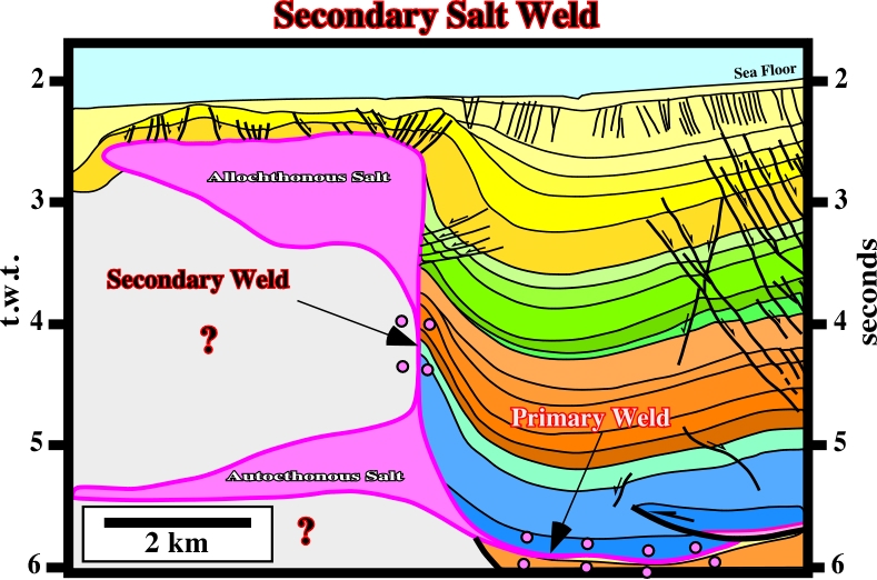
Secondary salt welds join strata originally separated by steep-sided salt diapirs (walls, stocks, etc.), and are near vertical or are steeply dipping. The salt feeding a spreading bulb or allochthonous sheet causes the diapir stem to shrink laterally and, eventually, thinning to negligible width or pinching off entirely (fig. 187), often by varying amounts of contraction.
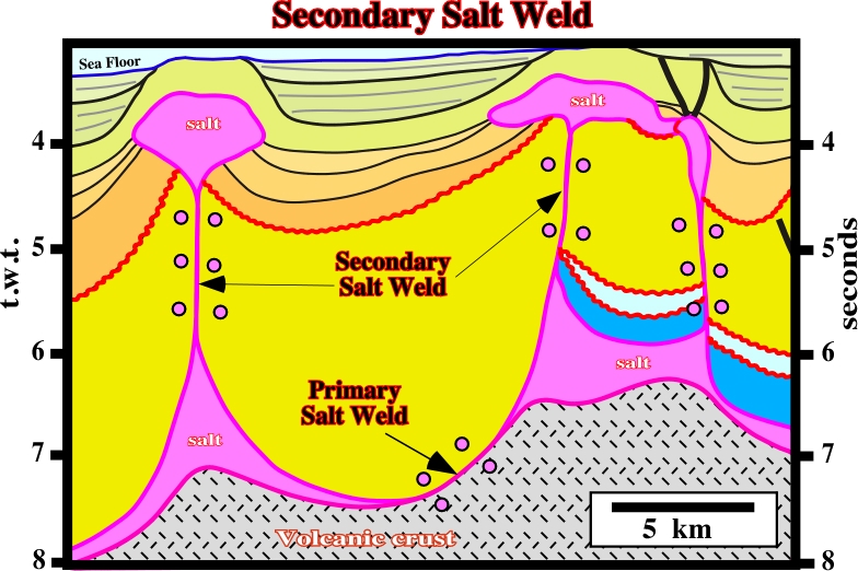
Fig. 187- On this tentative interpretation of an Angola offshore seismic line, the three salt bulbs seem to be connected with the autochthonous mother source layer by secondary welds. A primary salt weld, more or less horizontal and associated with the autochthonous salt is also recognized. Notice, that a late compressional tectonic regime, probably, associated with a ridge-push seems to have shortened the area where the seismic line was shot.
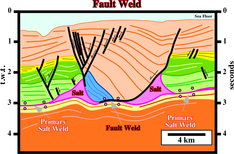
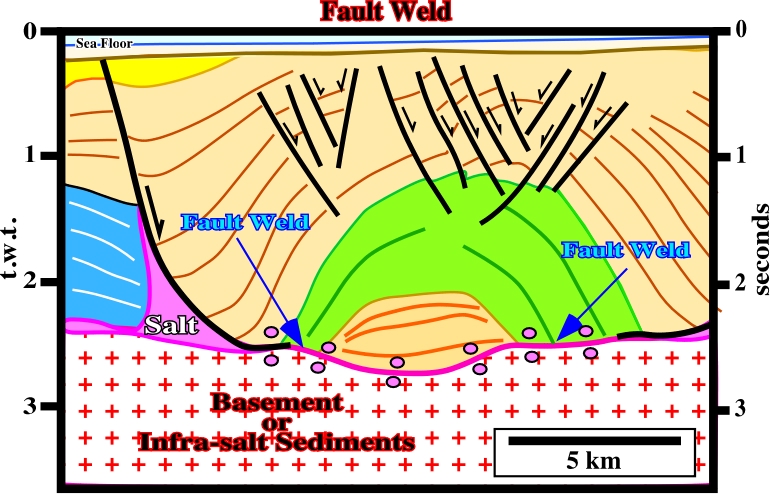
The overburden flanking each side of a diapir can be join, discordantly, together because diapiric growth is, usually, asymmetric. In such case, the salt weld resembles a growth-fault whether or not such a fault localized the formation of the diapir. This type of weld is often called fault weld.
Tertiary salt welds (fig. 191 and 192) join strata originally separated by a first order or higher allochthonous salt sheet (canopies, tongues, nappes, sills, etc.).
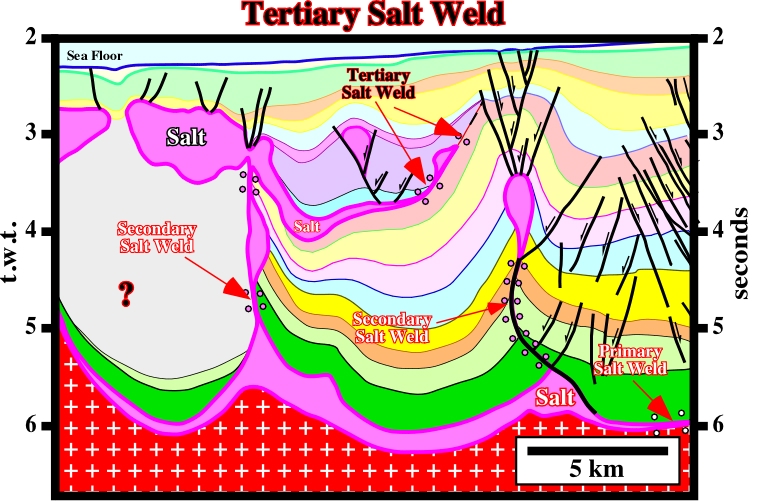
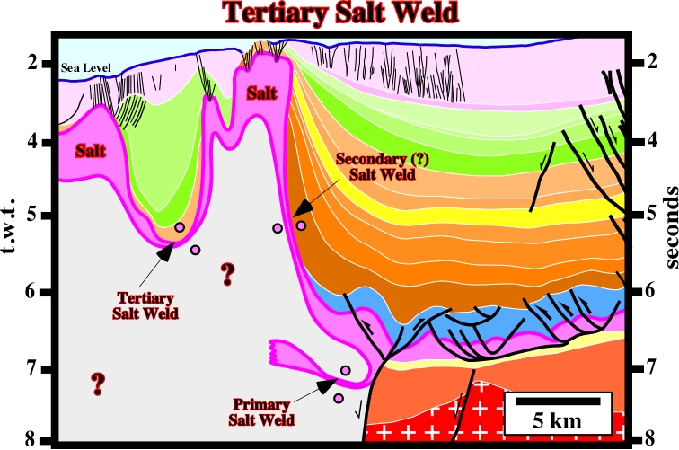
Tertiary welds are, generally, shallow dipping. They are typically discontinuous and inserted at unpredictable stratigraphic and structural levels. They are, particularly, useful to mark the former position of allochthonous salt sheet. Tertiary welds are, generally, overlain by highly extended cover and may be fronted by shortened strata, what leads to complex mixture of structural features on each side of the salt weld.
6.3- Recognition of Salt Welds
The recognition of a salt weld, as schematized on fig. 193, is quite important to understand the geology of salt basins and the associated petroleum systems.
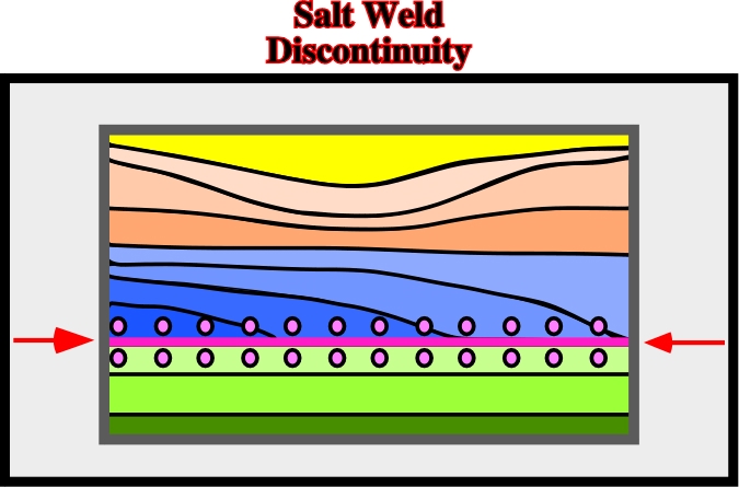
Fig. 194- On Angola offshore, for instance, when welding and fault welds are combined with extension (lengthening), as illustrated on this tentative interpretation, one should not over-estimate the salt reduction (mass transfer of salt over time, resulting in an obvious change in area of salt in cross section, by: (1) Volume loss due to dissolution, (2) Isochoric flow (unchanged volume) out of the plane of section, including smearing along decollement faults and (3) Isochoric flow within the plane of section but beyond the ends of the cross section. (see later).
A salt weld is a surface joining rock volumes formerly separated by salt as illustrated in fig 195.
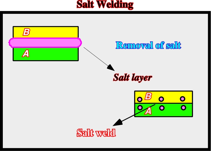
Fig. 196- On this tentative interpretation of a Black Sea seismic line, in spite of the geometry of the syn-kinematic layer (in yellow), the salt welds recognized on this line do not involve a significant lateral displacement. Petroleum exploration wells crossing primary salt welds found a thin salt interval under seismic resolution..
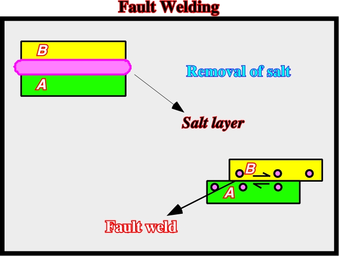
Fig. 197- In a fault weld (compare with fig. 195), which implies a relative lateral displacement between the overburden and the infra-salt strata, the salt removal is related to seismic resolution (fig. 198).
Fig. 198- In certain areas of the Kwanza and Congo geographic basins (Angola offshore), an extensional tectonic regime is, often, associated with halokinesis. Salt tectonics becomes dominant (any tectonic deformation involving salt or other evaporites, as a mobile layer, in this sense, salt tectonics is not a synonym of halokinesis. In fact, not all structures can be explained just by halokinesis ( deformation powered entirely by gravity, i.e., by buoyancy, in absence of significant tectonic stress (σt= 0), i.e., in an equilibrium tectonic regime. However, it must be noticed that halokinesis is, often, associated with an extensional tectonic regime (lengthening, σ1 vertical), but rarely with a compressional tectonic regime (shortening, σ1. horizontal). On this tentative one can recognize: (i) primary welds, (ii) growth faults, (iii) fault welds, (iv) roll-overs and (v) compensation grabens, (see next chapter).
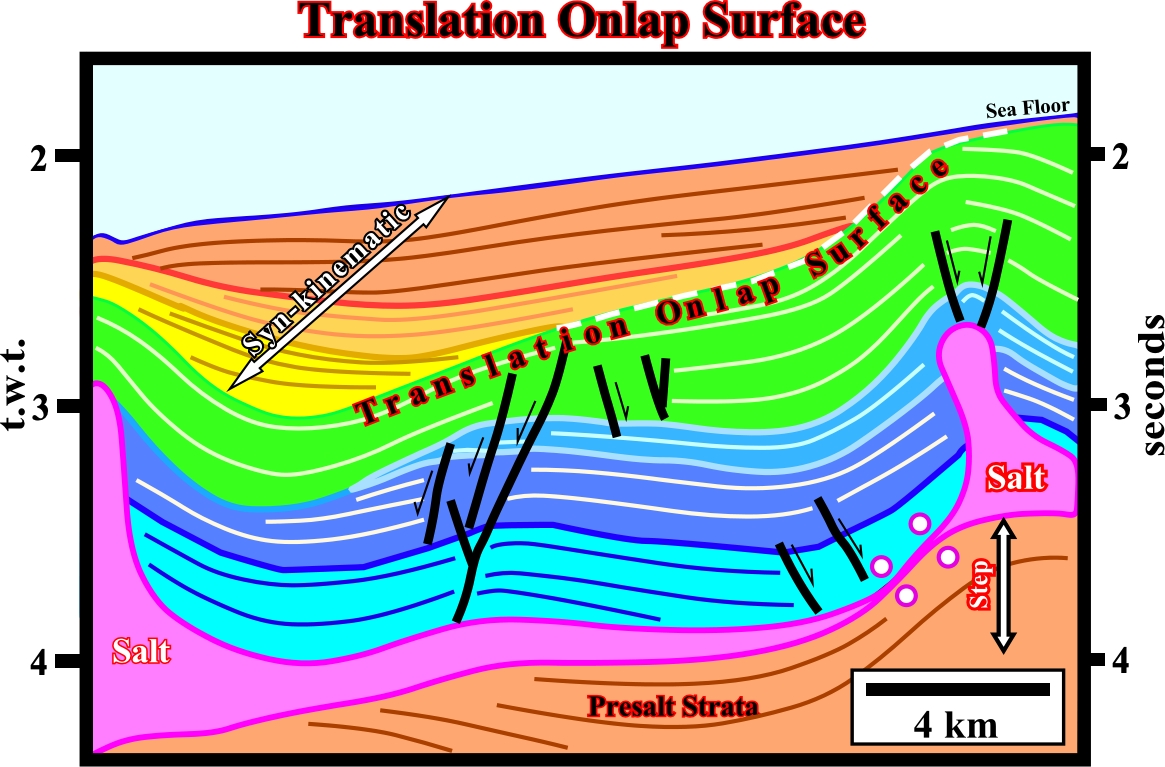
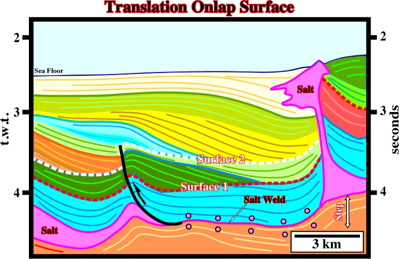
6.5- Translation Onlap Surfaces
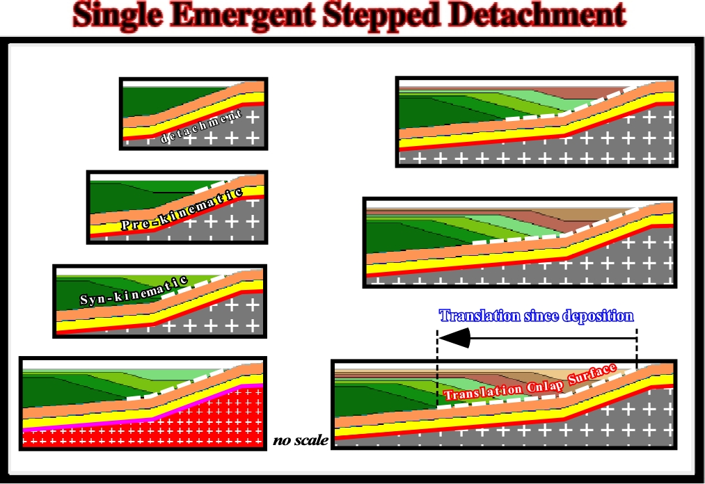
Translation of the overburden across a stepped salt detachment (thin salt) bends the post-salt sediments and can create apparent translation downlap surfaces (gliding onlaps) in the syn-kinematic layers (fig. 199 to 201).
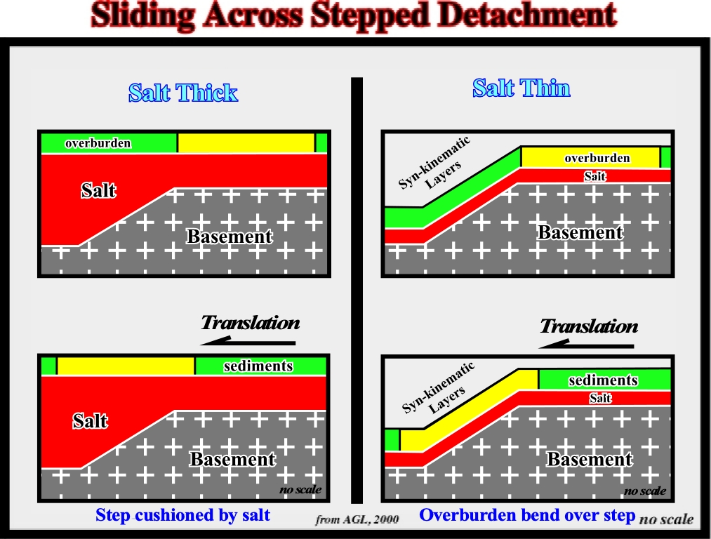
Summing up, the key points of overburden translation over a single buried step can be summarized as follows:
a) If the sedimentation rate is insufficient to cover the bathymetric escarpment, each unit will onlap above the step.
b) Onlaps are translated basinward after deposition, producing a landward-dipping package of onlapping strata (apparent downlap surface).
c) The distance from a given onlap to the step records the amount of translation since the deposition of that unit.
d) As older depocenters are translated basinward, younger depocenters form at the step. Continued translation produces a shingled series of landward-dipping stratal units, bounded by two growth axial surfaces.
c) The distance between the step and the intersection of a horizon with the landward growth axial surface records the translation since the deposition of that horizon.
d) For a given translation rate, faster sedimentation produces steeper growth axial surfaces.
On this subject, it is interesting to note that the salt steps recognized in the offshore Angola (previous examples) seem to correspond to the fracture zones (see later) separating the different geological provinces of the South Atlantic-type divergent margins. However, on the tentative interpretation of a seismic line (Angola offshore) illustrated on fig. 203, apparently does show any evident translation onlap surface.
to continue press
next
![]()