
Part I- Basic Principles in Salt Tectonics
Contents:
9.1- Extension9.1.1- Timing of Extension
9.2- Welding
9.4- Distinguishing between Extension, Welding and Extension Plus Welding
The sketch below (fig. 221) depicts the main characteristics of a regional extension (halokinesis excluded):
(i) Extension (lengthening) is the consequence of an extensional tectonic regime, i.e., a tectonic regime characterized by an ellipsoid of the effective stresses with a σ1 vertical.
(ii) The only way to extend, or lengthen sediments, is by normal faulting.
(iii) Normal faults will strike parallel to σ2., i.e., they are parallel to the intermediate effective stress (σ2) of the ellipsoid.
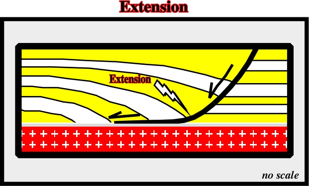
(iv) The hade of the normal-faults decreases with depth. Faults with such geometry are often, erroneously, called listric normal-faults (etymologically, the term listric fault was used to describe a fault not only with a curvilinear cartography but also with normal fault geometry, in the upper part, and reverse fault geometry, in the lower part, such geometry is typical of the faults created by gliding when the pore pressure becomes big enough). The term listric derives from the listron, that in Greek means shovel.
(v) The extension takes place only in the down-thrown fault block.
(vi) There is no extension or thickening of the sedimentary intervals in the up-thrown block, as illustrated in fig. 222 and 223.
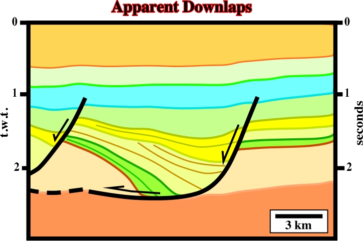
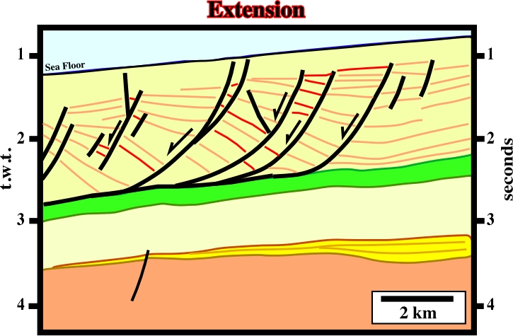
Fig. 222- On this tentative interpretation of a seismic line from Ikpikpuk Umiat geographic basin (North Alaska), extension is obvious. The basin had undergone a syn-sedimentary extensional tectonic regime above a décollement surface. The tectonic regime being characterized by σ1 vertical and σ2 striking N-S, the seismic line is a dip line. The normal-fault, limiting the extended area, is curvilinear and flat on the décollement surface. The sediments in the up-thrown block are undeformed corroborating in the geological model illustrated in fig. 221.
In petroleum exploration, one of the most important hydrocarbon parameters is the age of trapping. Very often, and particularly when the trapping is morphological by juxtaposition (as said previously, this kind of trapping is often, erroneously, called « fault trap »), dry wells can be explain by the trapping timing: “traps must exist when hydrocarbon migration takes places”. In basins with evaporitic layers, often, extension produces salt flow that can induce explorationists to inaccurately date the extension time. The hydrocarbon parameter “migration time versus trapping” is utterly important, as illustrated below in Southern North Sea example.
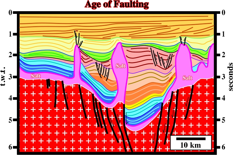
Following the Magoon’s terminology, in Southern North Sea, the more likely petroleum system is known and it can be abbreviated as: “Paleozoic / Paleozoic ”. The generating petroleum sub-system is Paleozoic and the potential reservoirs are the Lower and Middle Permian sandstones (Rothliegende formation), which underlie the Zechstein (Upper Permian salt). In addition, knowing that the more likely hydrocarbon migration time, in this geographic basin, is Upper Cretaceous, explorationists must put in evidence pre-Cretaceous traps to have a change to discover HC accumulations. Therefore, on the tentative interpretation of the seismic lines of this area, as illustrated on fig. 224, the key hydrocarbon parameter is to determine the age of the normal-faults. The potential traps are morphological by juxtaposition associated with fault displacement.
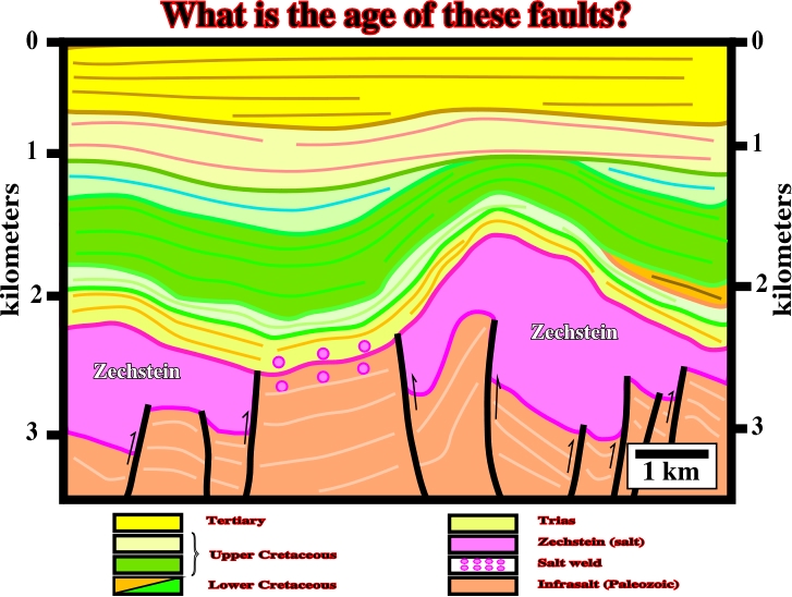
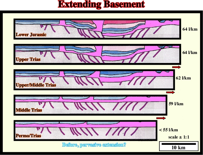
Fig. 224- Using this tentative interpretation (North Sea) to know the age of the picked faults, geoscientists must decide what is the more likely way to create accommodation (space available to sedimentation) knowing that two main hypotheses can be invoked: (A) Extension before or during salt deposition or (B) Extension after salt deposition. With the observed data, a geoscientist must falsify both hypotheses and choose the more difficult to refute. However, to test the geological hypotheses, they must know them (“Theory precedes Observation, K. Popper, 1934), what is not always the case.
Hypothesis A & Hypothesis B
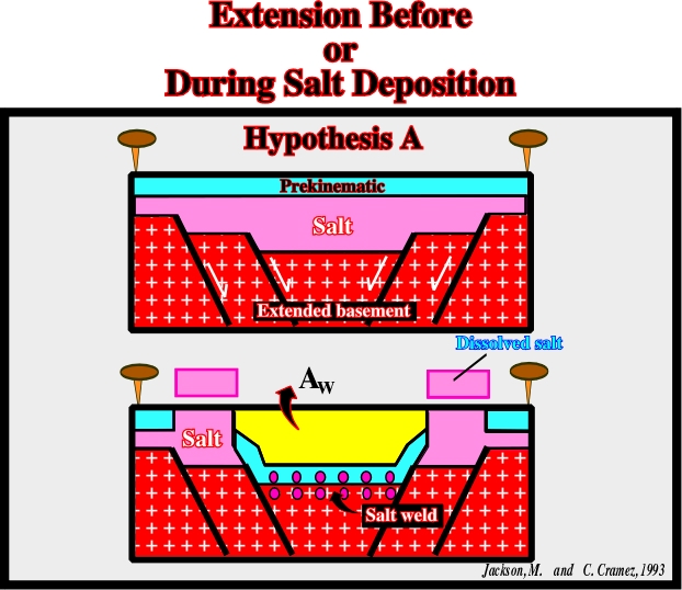
The hypothesis A, in which extension occurs before or during salt deposition, is depicted in fig. 225.
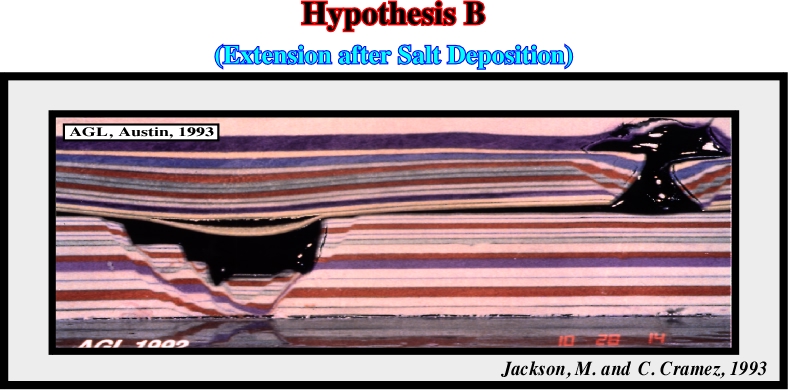
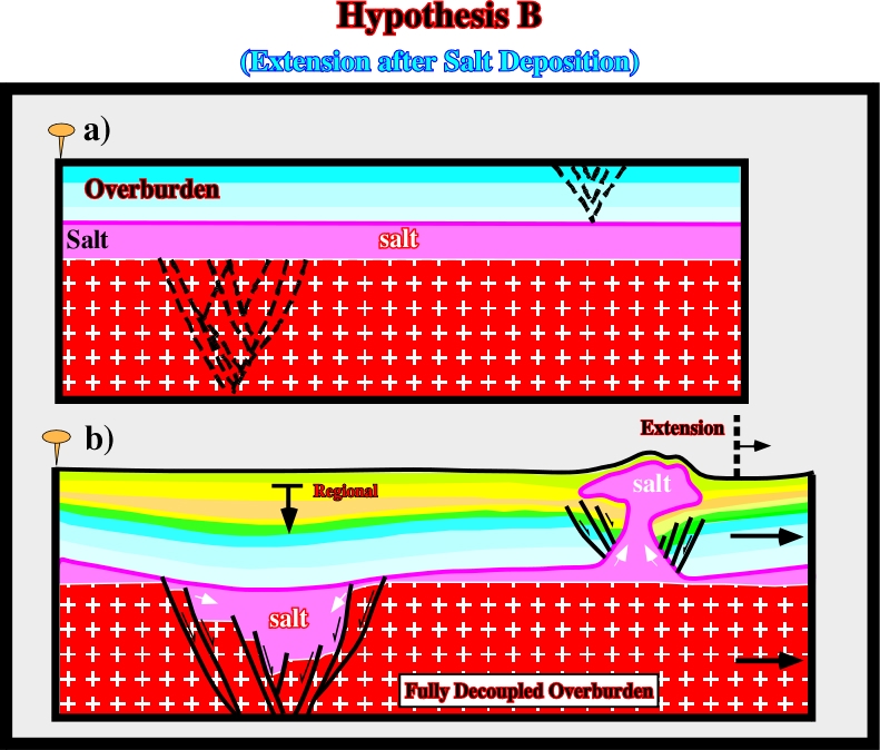
The hypothesis B, in which extension takes place after the deposition of the salt, is depicted in fig. 226.
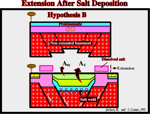
The hypothesis B can be summarized as follows:
- There is no extension before the salt deposition.
- The salt was deposited in a more or less horizontal and continuous stratigraphic layer.
- Overlying the salt, isopachous sedimentary intervals were deposited (pre-kinematic layers).
- A regional extension took place and reactivated, as normal faults, the pre-existent faults or fracture zones of the infra-salt strata.
- The salt flowed laterally and downward filling the space created by lengthening.
- Such a salt flowage induced in the overburden (above the pre-kinematic layers) a depocenter as well as a tectonic disharmony and a salt weld.
- A regional compressional tectonic regime took place and thereof the cover was shortened.
- The compression could locally reactivate the salt layer initiating a halokinetic phase.
Summing up:
(i) The faults post-date the salt deposition.
(ii) The faults post-date the pre-kinematic layer.
(iii) The associated morphological by juxtaposition traps post-date the hydrocarbon migration.
The hydrocarbon exploration implications of these hypotheses are contradictory. Centrifuge models were performed in order to test if the distinguished characteristics could be applied on seismic data (fig. 227 and fig. 230).
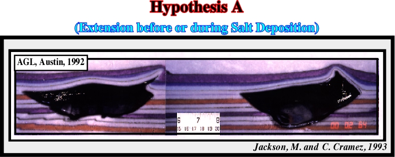
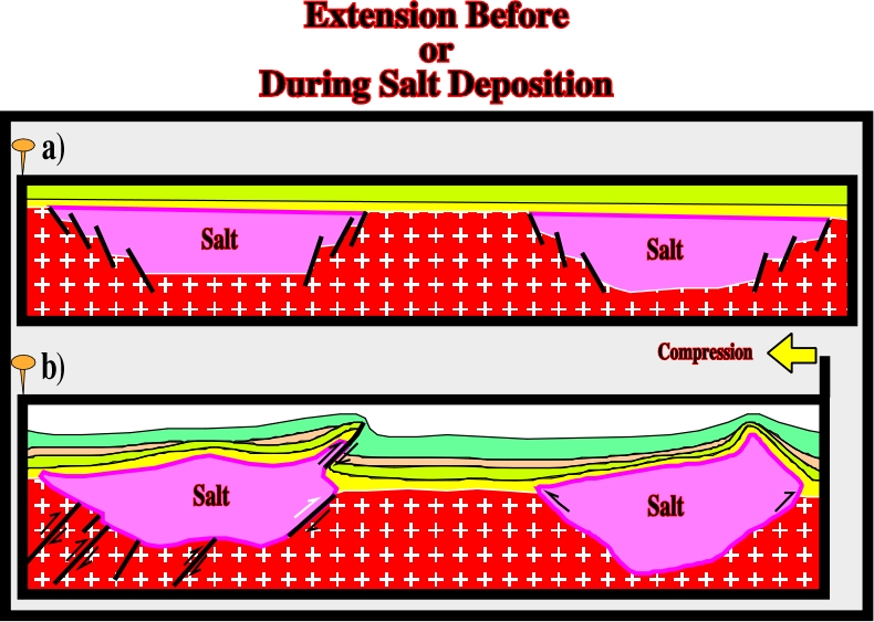
The centrifuge model of hypothesis A suggests that the final result does not fit the geometry observed on the tentative interpretation of the seismic lines (fig. 224). Indeed,
- On the model, the faults show a reverse geometry. However, such geometry is not observed on the seismic line (fig. 224), in which:
(i) In spite of the fact that they keep their original normal geometry, the faults are reverse.
(ii) The reactivation, during the compressional tectonic regime, was not enough to change their geometry completely.
(iii) The null point is too high on the fault plane.
- On the model, the majority of the faults dip toward the same direction, what is not the case on the tentative interpretations.
- On the model, there is a thrust-fault with the salt in the up-thrown block. There is no thrusting on the tentative interpretations (fig. 224).
- On the tentative interpretation, the inverted grabens are filled by salt, which is not the case on the model.
- On the model, the sedimentary layers are isopachous. They are pre-kinematic. On the tentative interpretations, there is a sharp thickness variation allowing the division of the overburden into pre-kinematic, syn-kinematic and post-kinematic
In conclusion: The model B seems to corroborate the hypothesis of a post-salt extension, which tell us that the faults on the seismic data are posterior to the salt deposition and, subsequently, the associated traps are probably posterior to the migration of the generated hydrocarbons.
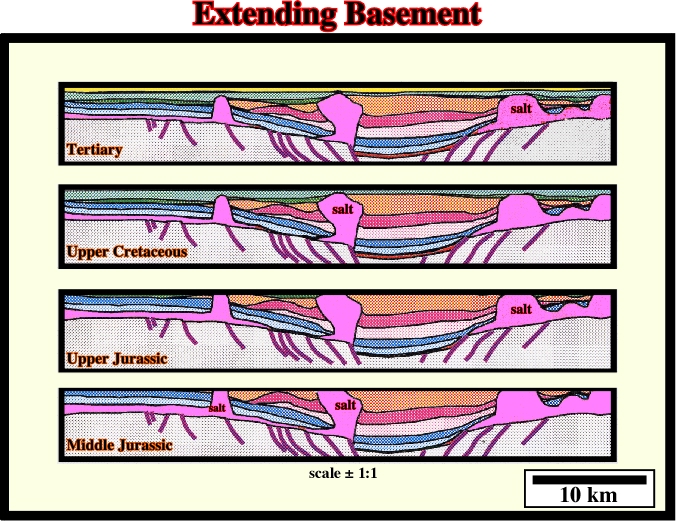
Restoration Test:
Similarly, the tentative geological interpretation of a North Sea seismic line seismic line illustrated on fig. 231 poses the same problem to the geoscientist. What is the age of the faults? What is the age of the sub-salt traps? These questions are paramount. In the area, the hydrocarbon migration of the main petroleum system is largely post-salt.
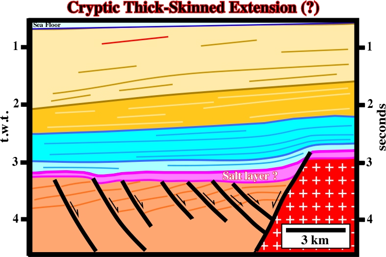
9.1.2- Cryptic Thick-Skinned Extension
Several years ago, Sheeval and Dale (1989) proposed a thick-skinned extension in offshore Cabinda (Angola). The geological sketch shown in fig. 234 illustrated this type of extension.
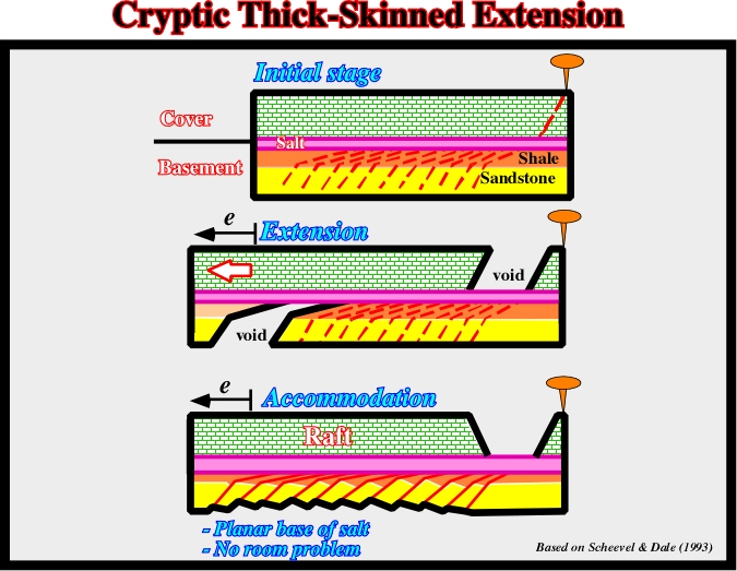
The cryptic thick-skinned can be summarized as follows (fig. 235):
a) In an initial stage, three stratigraphic intervals are deposited, more or less, horizontally:
- Infra-salt strata, composed by shales and sandstones ;
- A salt layer ;- A pre-kinematic calcareous overburden.
b) In a second stage, all deposited stratigraphic intervals are lengthened by regional extensional tectonic regime:
- A normal fault propagates from the basement to the overburden through the salt layer.
- Two virtual potential voids are created: one in the overburden and the other on the infra-salt strata.
c) In a last phase (accommodation phase):
- Syn-kinematic sediments fill the potential void in the overburden and infra-salt sediments fill the potential void within the infrastructure. The infra-salt strata are extended by normal-faults in order to solve a space problem (Ex nihilo nihil, in nihilum nil pose reverti).
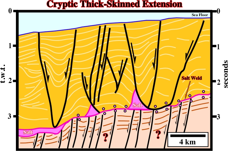
The figure below (fig. 237) illustrates a total salt reduction and the subsequent formation of a salt weld without regional extension.
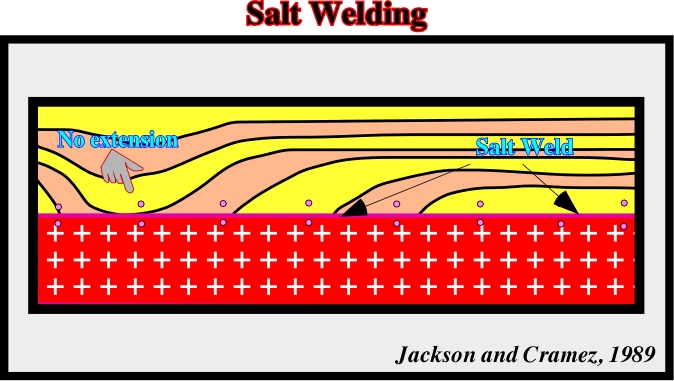
In fig. 237, the depocenter indicated by “no extension”, was created by total salt removal either of a salt roller or a small diapir. It is interesting to notice that in such an extreme case, the surface associated with the top of the salt (surface defined by reflection terminations) disappeared; it becomes coincident with the salt welding. The geometry of the chronostratigraphic lines can be interpreted as progradational package, that is to say, the geometrical relationships are not downlap, since the thickness between the two consecutive time lines increases progressively toward the discontinuity (fig 238). A real downlap relationship implies a seaward thinning since the interval becomes condensed down-dip (fig. 239).
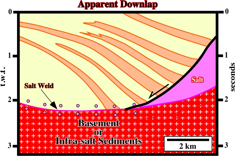
Fig. 238- On this tentative interpretation, the salt flowage created: (i) A compensatory subsidence ; (ii) A salt welding and (iii) An apparent downlap surface induced by a down and basinward gliding of the syn-kinematic layer onlap relationships.
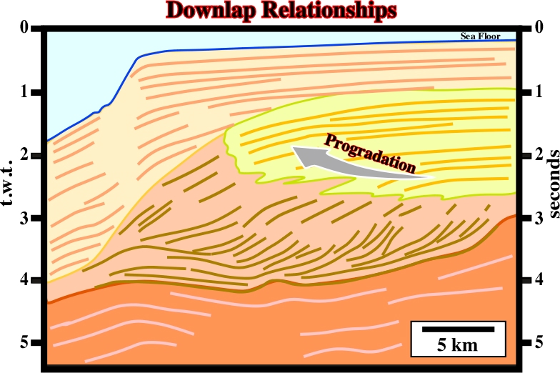
Fig. 239- Real downlap geometrical relationships between seismic markers are associated with progradational, or forestepping intervals, which seaward become condensed stratigraphic interval, as illustrated on this tentative interpretation of an Australia offshore seismic line. Notice, that the dipping reflectors (continental slope) define convergent down to basin internal configurations..
In the following geological sketch (fig. 240), the geometrical relationships suggest not only regional extension but a salt welding as well. In the down-thrown faulted block, there is extension and welding, while in the up-thrown faulted block only welding takes place.
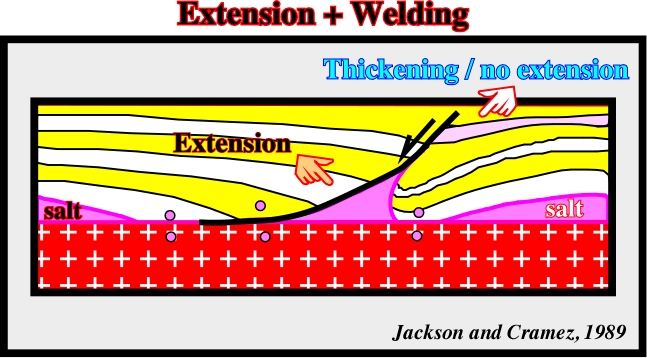
Fig. 240- On this sketch are summarized all characteristic geometrical relationships between the chronostratigraphic lines of a stratigraphic column that had undergone extension and salt welding.
On the other hand, it must be notice that in both faulted blocks of the above geological sketch, the stratigraphic intervals thicken toward the fault. On the up-thrown block, the thickening is just due to the withdrawal of the salt. Therefore no major regional extension is associated.
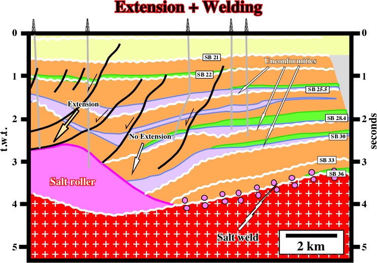
Fig. 241- On this tentative interpretation of a Texas onshore seismic line, extension occurs in the down-thrown faulted block of the main fault, while welding occurs in the up-thrown faulted block. On this tentative interpretation, the depocenter is induced by the salt flowage, which creates a big salt roller, which should not be confused with a salt diapir.
When extension and welding are combined (fig. 240), the continuation of the salt flowage breaks the salt continuity creating:
a) Two salt welds (one is a fault weld), and
b) A salt roller on the up-thrown faulted block.
9.4- Distinguish Extension from Welding
The major differences between (i) extension, (ii) extension + welding and (iii) welding are depicted on the three next geological sketches (figs. 242 to 244).
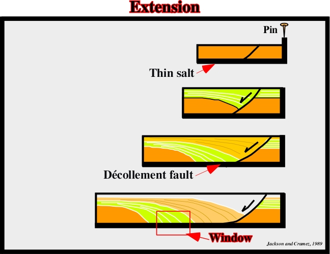
Fig. 242- In a pure extension over a thin salt layer, or along a décollement surface, apparent downlaps are developed against the tectonic disharmony (take a look at the window).
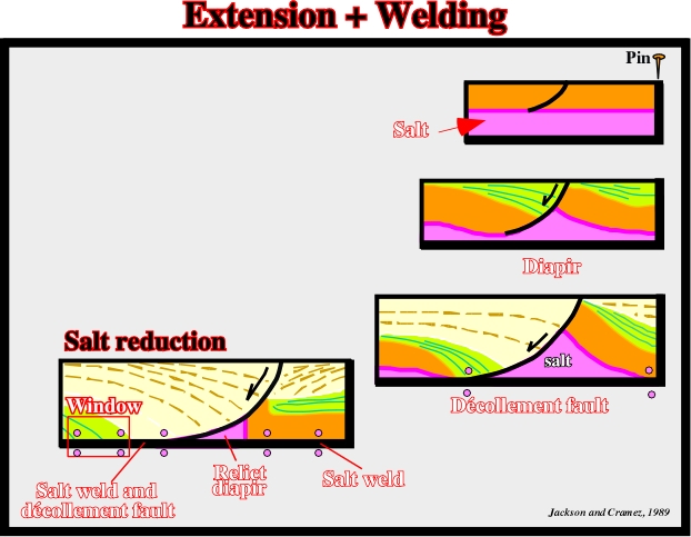
Fig. 243- Apparent downlap relationships are also developed when extension and welding take place. The window shows the same geometry as in previous figure, but correspond to a fault weld, i.e., to a surface or fault zone joining strata originally separated by autochthonous (on this example) . It is equivalent to a salt weld along which there has been significant slip or shear.
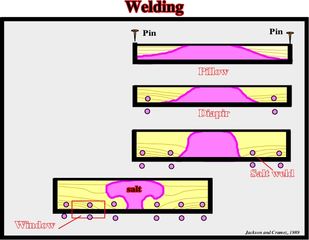
Fig. 244- In pure welding (halokinesis), apparent downlaps are also developed in association with the salt weld. Outside of the geological context, it is impossible to differentiate apparent downlap geometrical relationships induced by extension, from those created either by extension plus welding or just by welding. However, petroleum geoscientists cannot work in isolation and they just progress going from the general (theory) to the particular (observation).
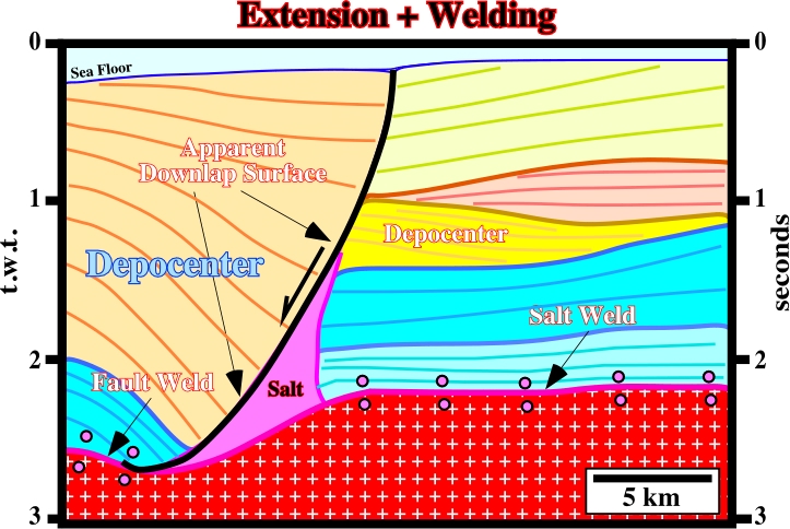
Fig. 245- On this tentative geological interpretation of a seismic line of Angola offshore, which regional setting is well known, the geometrical relationships between the seismic marker define seismic surfaces suggesting a regional extension. An extensional tectonic regime and salt welding, mainly induced by halokinesis, exist in thee area. A salt weld (halokinesis) is recognized in the up-thrown faulted block (foot-wall). A fault weld (salt tectonics) is recognized in the down-thrown faulted block (hanging-wall). Also, (i) an apparent downlap surface and a depocenter thickening toward the fault plane is recognized in the down-thrown faulted block (extension + welding), as well as, (ii) a depocenter, induced by shrinkage and partial collapse of the salt roller, thickening down-dip is recognized in the up-thrown faulted block block (halokinesis).
9.5- Rise and Reduction of a Diapir
To end this chapter, in the next figure (fig. 246), is illustrated the rising and reduction of a salt diapir. Notice that:
- There is an initial slope on the top of the salt layer ;
- Since the diapir rises, depocenters are formed, as well as, salt welds and rafts (see next chapter) ;
- The extension is underline by the fault heaves;
- When salt reduction starts, the central depocenter is initiated ;
- Continuation of salt reduction creates relict diapir, a primary salt weld and a décollement fault ;
- Chronostratigraphic lines and reflection terminations can be tilted.
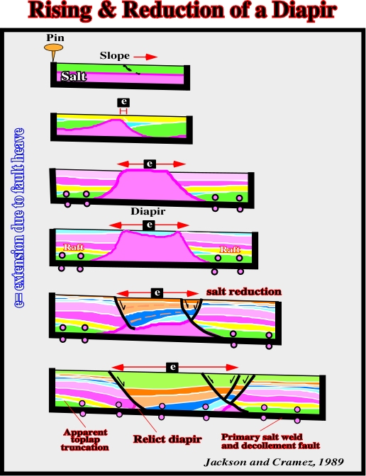
Fig. 246- In this geological evolution, one can see that by compensatory subsidence a depocenter is developed in the overburden at the place of the diapir. In the same way, as the salt flows away, generally down-dip, salt welds and rafts (see next chapter) are developed, as well as, a relict diapir. Very often, salt reduction is incomplete. The last stage (continuous salt weld) is not reached. The evolution can stop when a depocenter is developed on the top of the diapir. In certain basins, or in particular areas, characterized by local compressional regimes tectonic, inversions are possible. Shortened depocenters can be recognized on the top of diapirs (see fig. 247 and 248).
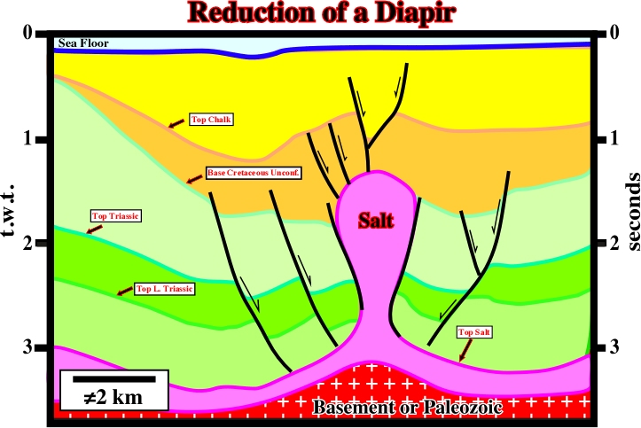
Fig. 247- In spite of the fact that in this tentative interpretation of a Southern North Sea seismic line, the vertical and horizontal scales are approximate, it is quite evident that the depocenter overlying the salt diapir was induced by a reduction of the salt structure. In fact, the depocenter thickens inward, i.e., toward the centre of the diapir. Later a slight compression shortened the depocenter creating a subtle inversion in the central part. Even more evident inversions of these depocenter are known in offshore Angola as illustrated in next figure.
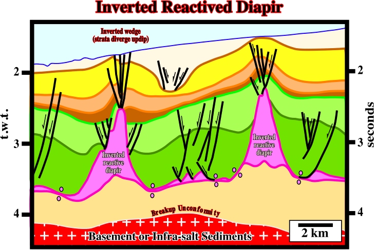
Fig. 248- The tectonic inversions of the depocenters in the overburden associated with diapir reductions are well know in offshore Angola, as illustrated on this tentative interpretation. Actually, when, a depocenter, that is to say, a convergent thickening interval, overlying a salt diapir, is in a high structural position, geoscientists must hypothesize a tectonic inversion induced by a local, or regional, compressional tectonic regime. Such a tectonic inversions can be associated with regional shortening or local reactivation of the old pre-existent fault or fracture as illustrated next (see fig. 249).
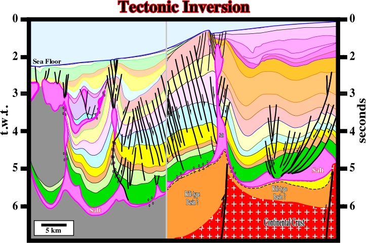
Fig. 249- On this tentative interpretation of an Angola offshore seismic line, the Tertiary reactivation of the pre-existent normal fault bordering a rift-type basin, created a tectonic inversion, easily, recognised on the bathymetry. A probable tectonic evolution of this structures illustrated on this tentative interpretation is proposed on fig. 254.
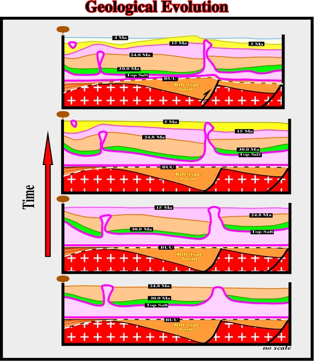
Fig. 250- In this tectonic evolution, it is hypothesized that the Late Tertiary shortening of the overburden it was induced by the reactivation, in reverse fault, of a pre-existent normal faulting bordering a rift-type basin, which is, easily, recognized in lengthened Gondwana continental under the BUU unconformity, which, obviously does match with the salt induced tectonic disharmony. Due to the reactivation, locally, the lower structural points become high and the high structural points become lower points.
to continue press
next
![]()