
Part I- Basic Principles in Salt Tectonics
Contents:
8.1- Depocenter and Apparent Mound
8.2- Inversion, Salt Roller, Relict Roller and Fault Weld
8.3- Apparent Downlaps
8.1- Depocenter and Apparent Mound
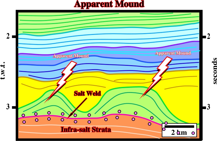
As illustrated in fig. 213, apparent mounds are, often, developed in association with salt welds.
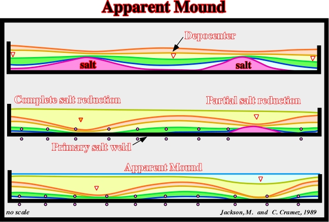
Fig. 213- On this geological sketch, inter-domal synforms become apparent mounds by complete salt evacuation, that is to say, by total evacuation of the salt. Depocenters become apparent mounds. They are inverted structures, in which the high structural points become low structural points
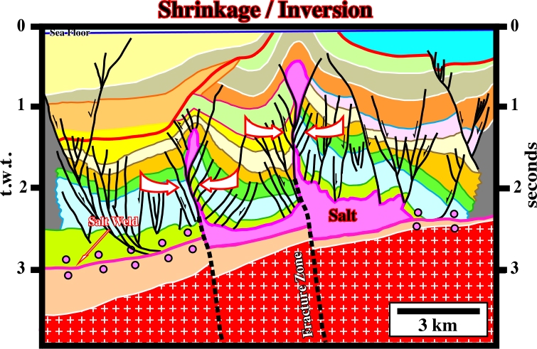
8.2- Inversion, Salt Roll-overs, Relict Rollers & Fault Welds
The geological sketch, illustrated in fig. 215, allow us to understand:
(i) How salt flowage can invert the fault movement of an associated growth-fault.
(ii) How a salt layer become a down-dip succession of salt rollers.
(iii) How a total salt reduction creates a salt weld and changes salt roller into relic salt rollers.
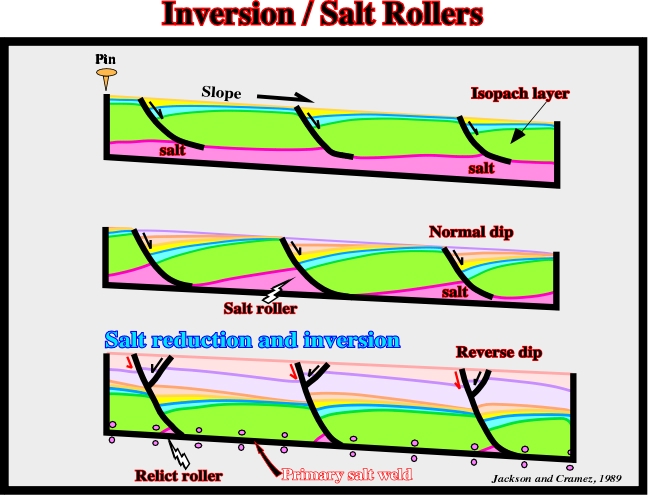
The geological evolution depicted on the sketch illustrated in fig. 215, can be summarized as follows:
a) Deposition of an isopachous pre-kinematic interval (in green) above the allochthonous salt layer (in purple).
b) Slight seaward tilting of the basin initiates salt flowage. Flowage creates small basinward growth-fault.
d) Syn-kinematic deposition of the blue and yellow intervals.
e) The thickness of the syn-kinematic intervals increases toward the growth-fault planes, where there is accumulation.
f) The continuation of salt flowage creates more space available for sediments in the down-thrown faulted block increasing the normal down-dip movement of the normal faults.
g) At a given degree of salt reduction, the previous continuous salt layer becomes a discontinuous layer composed of a succession of elongated prisms of salt, localized at the down-dip toes of the fault blocks.
h) Since the landward flanks of the salt rollers shrink, by withdrawal and salt flowage, the overburden collapses.
i) The collapse of the up-thrown sediments creates an inversion of the fault displacement. The faults play with a similar movement of those of the reverse faults. The fault movement and geometry of the faulted blocks should not be taken as an evidence of a compressional tectonic regime.
j) The inverse movement of the fault plane creates space and obliges the sediments of the down-thrown block to extend creating normal accommodation faults.
k) When salt reduction becomes almost total, the shrinkage of the salt roller creates relic rollers, which can be laterally disconnected, as illustrated in fig. 216.
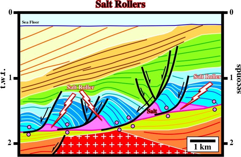
On the next theoretical geological sketch (fig. 217), it is illustrated the normal slip and the reverse dip created by salt reduction, when a salt dome becomes successively a salt roller and then a relic roller. Taking a look at the unconformity (in red) it is easy to recognize:
(i) At the stage of the salt diapir, the movement of the normal-faults is real normal.
(ii) Then the diapir shrinks and becomes a salt roller.
(iii) The unconformity shows a reverse position, i.e., its position is lower on the up-thrown faulted block than on the down-thrown block.
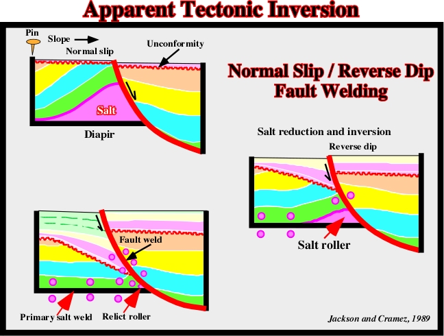
(iv) Finally, if the salt reduction is extreme, the salt roller becomes a relict roller and the inverse displacement is maximum.
(v) The evolution "salt diapir - relict roller" is accompanied by the formation of a fault weld, as illustrated in fig. 218.
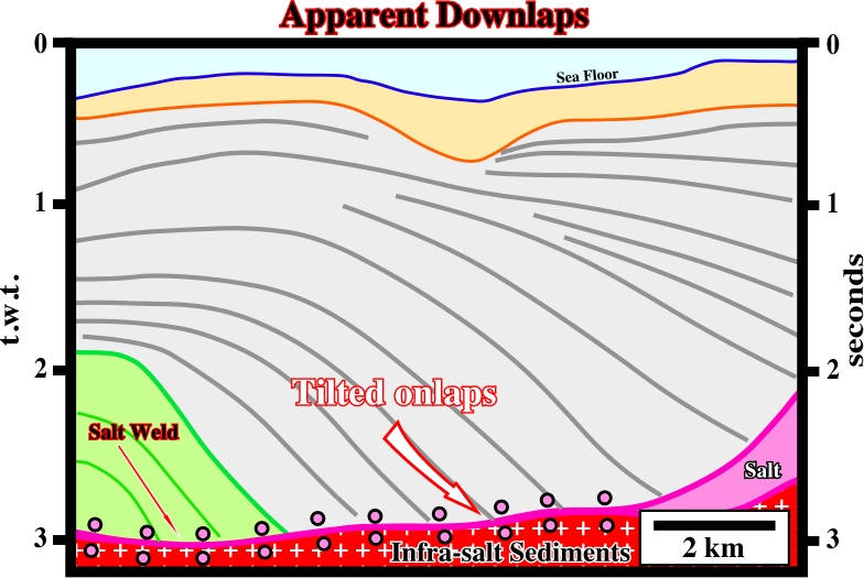
Salt reduction changes the original reflection terminations and, very often, it creates apparent downlap geometric relationships. The mechanism of such a change is illustrated on the figure below (fig. 219).
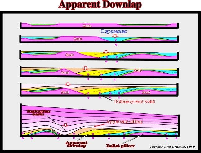
Fig. 219- On this evolution, the final geometrical relationships are apparent downlaps. The onlaps are, progressively, tilted toward the tectonic disharmony, due to the salt flowage. If the salt evacuation is total, the tectonic disharmony becomes a primary salt weld, as illustrated on next figure.
to continue press
next
![]()